|
Why do I want to upgrade the M2 Z motor from the silver frame to the black frame when the existing one works just fine? The answer is all about noise, accuracy and precision (and not about resolution) and a desire to update my M2D to the current Revision E.
The Z stage is always under load (this is Sir Isaac Newton’s fault). My understanding is that the old (silver framed) Z motor was driven with 8 micro-steps in a 1.8 degree pole step. The old lead screw allowed the Z stage to drop under its own weight until balanced by an increase in Z motor current.
The new Z axis lead screw has a finer pitch, reduced diameter and increased bearing length. These appear to prevent Z stage free-fall. The new (black framed) motor allows 16 micro-steps in a 1.8 degree pole step. So the Z motor holding current should be less than the original motor and any gravity drop should also be reduced. It would be reasonable to expect that the effects of drive noise on Z stage travel and resonance effects should also reduce.
If you are getting satisfactory prints with your current Z stage then there is no impetus to upgrade. However if you want to push the capabilities of the M2, upgrade your printer to the current revision, or if your old Z stage has died, then this upgrade may be warranted.
The Z axis parts arrived today: a new black Z motor complete with lead screw and a new Z stage with Y rail and 10 mm guide bearing installed. There is no MakerGear upgrade instruction for this, and the M2 kitset comes with the Z stage installed, so here’s my procedure.
The mounting for the new black motor has changed to three axial-concentric mounting bolts that do not align with the four frame holes for the silver motor. However the new motor will mount identically to the old motor (reusing the old bolts) without any machining of the frame.
Disassembly
1. Turn of and unplug the printer, remove any USB connection, and clear some bench space.
2. Remove any filament reel and unbolt the filament guide and the spool mount from the left side of the M2. This will allow you to lie the frame in a stable position on its left hand side for access to the underside without damaging anything.

Figure 1. Filament Guide and Spool Holder
3. Remove the glass retaining clips, the glass and the heated bed platen. Note that you do not need to disassemble the wiring loom at all for this upgrade.
4. Slacken off the Y axis motor mounting bolts (three) and remove the Y axis belt from the idler bearing.
5. Remove the Y axis end stop switch (two bolts).

Figure 2. Y Axis Motor and End Stop
6. Remove the spider from the Y axis linear bearing carriage (four bolts) and lift it clear with the Y axis belt. (Note that these were found to be very loose during disassembly. I’ll be applying some Loctite 222 when they are reassembled.

Figure 3. Spider Bolts to Linear Bearing Carriage
7. Remove the Y axis motor (three previously slacked bolts).
8. Remove the Z stop assembly from the rear guide rail (two bolts).

Figure 4. Z Stop Assembly
9. Disconnect the Z motor electrical connector.
10. Using the manual Z knob lower the Z stage to the near the bottom of its travel.
11. Remove the manual Z knob (slacken one bolt).
12. Slacken the lower and upper guide rod clamps (four bolts). This will require the frame to be placed on its side to access the clamps on the underside of the frame. Manually guide the X axis stage to the low point while tilting the frame.
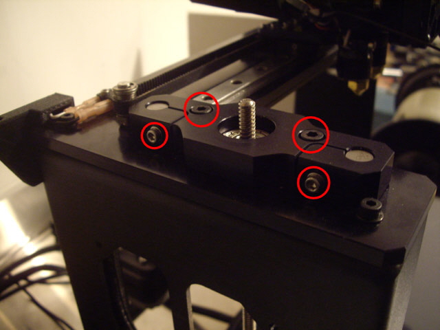
Figure 5. Top Guide Rod Clamp Bolts (horizontal) and Clamp Retaining Bolts (vertical)
13. With the frame still on its side, remove the Z motor mounting bolts (four).
14. Gently ease the Z axis guide rails (two) towards the top of the frame until they clear the Z stage bearings. They do not need to be fully removed from the frame. If the guide rails do not move freely from the frame then re-tighten the top guide rod clamps (two bolts) and undo the top clamp retaining bolts and associated lock nuts. Then, using a large flat bladed screw driver with a suitable spacer to prevent scratching the frame, gently pry between the top of the frame and the clamp mounting bolt heads. The Z motor may lift from the frame and the Z axis lead screw bearing should pop free from its recess in the top clamp. Note that the guide rails and lead screw are lubricated components. Handle appropriately to avoid covering everything in grease.

Figure 6. Guide Rods Lifted Clear of Y Stage
15. Remove the Z axis motor, lead screw and stage from the frame, disengage the lead screw and remove the Z end stop buffer washer.
Assembly
1. Remove the new Z motor case bolts (four).
2. Place the old Z stop buffer washer to the top of the new motor. Note that this washer is the wrong size for the new lead screw but it should still be functional.
3. Feed the lead screw into the new Z stage until the stage is near the motor (at the bottom of the lead screw).
4. Ease the Z motor and lead screw into position with the motor electrical connection to the right.
5. Feed the guide rods gently through their respective Z stage bearings into the bottom clamp.
6. Hand tighten the Z motor into position from the bottom of the frame using the four original motor mounting bolts. Work on opposite diagonals gradually tightening the bolts to keep stuff flat.
7. Fit the two top clamp retaining bolts and lock nuts if these were removed. Then tighten the four guide rail camp bolts.
8. Check that the lead screw is central in the upper clamp lead screw hole throughout the Z stage travel by manually turning the lead screw. Start with the stage at the top of travel (near Z zero). If the lead screw is off centre with the Z stage high then the Z stage lead screw bearing is not aligned correctly (there is almost no play in the guide rods and the clamp mounts). Loosen the bearing bolts on the Z stage and try turning the bearing through 120 and 240 degrees, and pressing horizontally towards centre. If the shaft will not align then liaise with MakerGear.
9. Now move the Z stage to near the bottom of travel. Any eccentricity in the lead shaft movement at the upper clamp lead screw hole is due to a bent lead screw. This can be straightened or liaise with MakerGear for a replacement part. If the lead screw is consistently off centre in one direction then either the motor shaft is not perpendicular to the case or it is off centre. Loosen the motor mounting bolts and see if the problem is resolved. If not apply finger pressure to the motor to move and tilt it. Try turning the motor through +/- 90 degrees and try some shim between the motor and the frame to see if these will correct the alignment. If the shaft will not align then liaise with MakerGear.

Figure 7. Lead Screw on Dead Centre Throughout Z Stage Travel
10. Progressively tighten any loosened bolts to maintain the lead screw alignment.
11. Fit a new lead screw support bearing at the top of the frame. Note that the old bearing is the wrong internal diameter for the new lead screw.
12. Move the Z stop actuator bolt from the old to the new Y stage.
13. Move the Y axis belt idler from the old to the new Y stage.
Now work the disassembly procedure in reverse from step 11 to step 1 above. There is nothing critical here, just take your time, do not force stuff, and use appropriate tools.
At the end of this procedure I found that I needed four additional parts to complete the upgrade. The lead screw support bearing at the top of the frame, the Z axis rubber stop washer, and the manual Z axis knob all need to be replaced to suit the new lead screw diameter. And most importantly the old Z motor plug does not fit the socket on the new motor. I can’t be printing anything without the bearing or an appropriate motor plug.
MakerGear have kindly shipped the parts that I’m missing to complete the Z motor upgrade but they’re being sent by USPS so I’ll be waiting a while for these to arrive.
There are some tests, alignment and lubrication to complete. Set the Y axis belt tension. Check the operation of the Y and Z motor drives. Check the operation of the Y axis end stop. Level the bed and set the Z axis end stop. Lubricate the Y rail, the Y belt idler, the Z lead screw and the guides.
The missing parts have arrived (less two machine screws and nuts). The new Z lead screw bearing is not actually a replacement but the same size as the original with a nylon sleeve insert. This was how I had contemplated modifying the original (except with brass). The new bearing simply drops into the top of the frame.

Figure 8. New Bearing Insert
The new low profile Z axis knob fits on top of the lead screw with about 2 mm clearance to the top of the frame. Note that the grub screw on the new knob is not aligned radially and appears to have a 5/64” hex head.

Figure 9. New Low Profile Z Knob
MakerGear have sent an entire new Z stage loom. This supports a bottom Z stop so either I need to remove the old top Z stop or strip and reassemble both looms to incorporate the the new Z motor plug in the old loom. The Revision E M2 has a bottom end stop so I’ll be using the new loom, moving the Z stop, and getting accustomed to a new bed height setting procedure. This will necessitate a further firmware upgrade to Revision E.
Replacing the loom and moving the Z stop to the base of the printer was quite straight forward.
1. Undo the original Z micro-switch and LED stop bracket from the top of the rear Z axis guide rail (two bolts). See Figure 4 above.
2. Cut the cable ties (five) on the Z cable loom. Take care to avoid cutting anything but the cables ties. You will need some replacement ties.
3. Remove the left hand filament guide (two bolts) and the X zero micro-switch (two bolts).
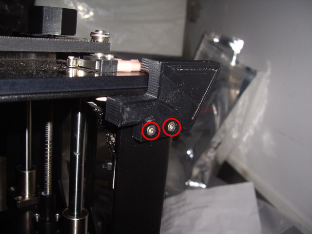
Figure 10. Left Hand Filament Guide
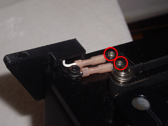
Figure 11. X Zero Micro-switch
4. Remove the RAMBo electronics case lid (three bolts).
5. Remove the Z axis loom from the frame and the RAMBo.

Figure 12. Original Three RAMBo Z Loom Connections
6. Route the new loom and fit the connectors to the appropriate plugs in the RAMBo. Note that the Z motor plug polarity on my M2 has the red wire to the rear of the RAMBo (in accordance with the original M2 wiring instructions) but this contradicts the wiring polarity in the RAMBo manual. This plug is not polarized and it will fit either way around. The motor will still work if you have got it wrong but it will drive in the wrong direction. My Z motor drives in the correct direction (+Z is downward) with the red wire to the rear.
The Z zero has changed from Z min to Z max. So fit the Z stop plug in the socket immediately to the right of the old Z stop location and note that the polarity of this plug is 180 degrees from the original. If you get this wrong then the Z motor will drive to the maximum stop (downward) and then freeze.

Figure 13. New Z Motor Connection (Note Polarity - Red Wire to Rear))

Figure 14. New Z and X Stop Connections (Note Polarity and Location)
7. Press an appropriately sized nut into the hex mounting recess on the new Z stop bracket. Fit the new Z stop bracket to the bottom of the rear Z axis guide rail (one bolt - not supplied) with the micro-switch facing forwards (towards the front of the printer). The bracket needs to be firmly pressed onto the guide rail. Slide the bracket down to the base of the printer and check that the micro-switch activates from the underside of the Z stage before this collides with the electronics case. If necessary move it upward. Note: if the bracket is seated against the base of the printed then it cannot move anywhere when the Z stage is zeroed. Tighten the mounting bolt to secure the stop mounting bracket.
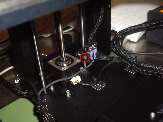
Figure 13. Fitting the New Z Zero Micro-Switch
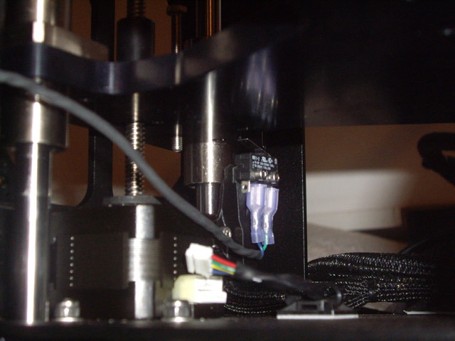
Figure 14. Z Axis Zero Micro-switch Actuated by Z Stage
8. Remove the old Z zero activation bolt and lock nut (one of each) which are now redundant.
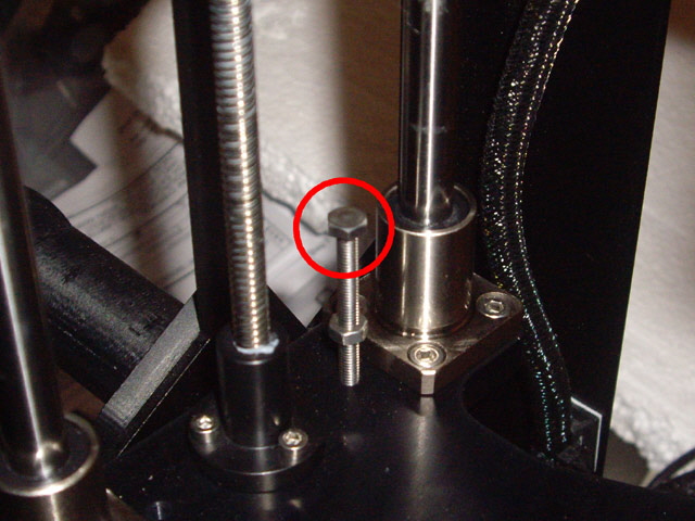
Figure 15. Old Z Zero Activation Bolt and Lock Nut
9. Plug in the new Z motor.
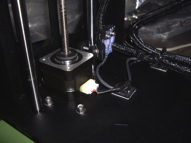
Figure 16. New Z Motor Plug Attached
10. Refit the new X axis zero micro-switch (two bolts) and the original left hand filament guide (two bolts) routing the wires carefully to avoid pinching between the guide and the frame. See Figures 10 and 11above.
11. Adjust the new Z cable loom so it is tidy and not stressed. Secure the loom with new cable ties (five) and trim these.
12. Double check the seating and polarity of all RAMBo connectors and refit the case lid (three bolts) ensuring that the cooling fan is not obstructed by the wiring in the case.
13. Omitted due to superstition.
14. The Z stage hardware modifications are now complete. The RAMBo firmware now needs to be upgraded before testing the Z stage movement, and the Z and X axes zero micro-switches using your preferred software interface (I use Protoface). MakerGear have a range of firmware upgrades that will support your M2 with the new black framed Z motor, three or four point levelling, single or dual extruders, and with or without an LCD controller. If you can’t find the right firmware upgrade then contact MakerGear technical support.
15. Now check the Z motor, Z and X stops using your favourite interface. Manually position the extruder in the centre of the bed at about half the Z travel. Turn on the M2 and connect. Now make small positive (downward) and negative movements on the Z drive. Make sure that the drive is moving in the appropriate direction. If it is wrong then you will need to change the polarity of the Z motor connector in the RAMBo. With your finger near the M2 power button try the Z home. The Z stage should descend to the micro-switch, rise a few mm and descend again. If the Z stage tries to drive through the base of the machine turn off the M2 power. Then double check that the Z stop micro-switch is connected to the maximum zero plug in the RAMBo. If the Z stage lowers to the micro-switch and then won’t move you have got the polarity of the Z stop plug 180 degrees wrong in the RAMBo.
You will need to level the bed and calibrate the Z offset before staring printing.
Click here for levelling guidance for three point spider (Rev. D) and and four point Heated Bed Platforms (Rev. E). While I have yet to work through the bed offset procedure, everything appears to be working.
The new Z stage needs to be calibrated to ensure that the HBP raised to the appropriate height for the first print layer. Click here to navigate to my X, Y and Z calibration procedure for an M2E.
If you haven’t done so already now is a good time to clean and re-lubricate your M2 and adjust the tension of the X and Y axis drive belts.
I have completed my first print with the new Z stage. This was a medium resolution print with optimized layer start positions.

Figure 17. First Print
The good news is that the print quality is entirely acceptable although there are a few issues with the model design. Vertical surfaces look nice and smooth with the exception of a repeating 0.25 mm high point at the layer start (easily fixed with random layer start positions). There is some extruder over-compression on the top layer but far less than I’ve seen on commercially 3D printed parts. There is also some jitter at sharp edges (an acceleration setting issue which can also be resolved by reduced outer layer print speed) but no ghosting.

Figure 18. Layer Start Point Ripple
Is the print better quality than I would have achieved with my old z motor? It is up there with some of the best medium resolution prints that I have every done and I have yet to start tweaking my print parameters.
If you have any questions, comments or suggestions please email me. I will respond. Otherwise click here to navigate to installing a dual extruder...
|