|
What to Print?
I have no need for the standard models that come on the SD Card and I’d like to improve the fan mounting and maybe make a dial gauge indicator mount to assist with levelling the bed. I have a heap of my own parts that I would like to print but I expect that I’m best to start with something relatively small and not too complicated. Starting a design from scratch will also get me acquainted with producing the gcode.
One of the main uses for lathes, mills and 3D printers is making replacement parts or accessories for lathes, mills and 3D printers. There are a number of suggested improved fan mounting brackets and a dial indicator gauge mount that you can find on ‘Thingiverse’. However I decided to design my own based on the standard bracket with an extension to mount a dial indicator gauge without removing the fan assembly.
Click here to navigate to the fan bracket design, printing and testing.
- When setting to the Z home position make sure that there is no extruded plastic on the end of the nozzle.
- Check the Z home position and bed level from time to time. It takes just a few minutes.
There is probably an recommended method for cleaning the exterior of the extruder nozzle, but making it hot and wiping it with brass wool worked for me.
Note that the Z home position clearance that you set will depend on the printed layer height and this will vary depending on on your specific model layer settings. On the M2 a high quality print will have a layer height of 0.1 mm with the default 0.35 mm diameter extruder nozzle. My Z home clearance is between 0.102 and 0.127 mm across the bed. The initial print layer must adhere well to the bed or the printed part may detach and the print will fail.
- Set the Z home position clearance for the print layer height which varies depending on the print quality setting.
I am now ready to embark on printing the list of stuff that I purchased this printer for. This includes instrument cases, prototype OEM plugs, lever arms for my coil winder, replacement plastic components for an antiquated radio, a laser housing, bits for my welder plasma hand-piece, retort clamps, reagent bottle fasteners …
Here are some of my first prints.
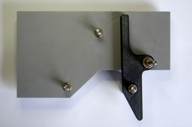
Figure 4. Lever Arm for Coil Winder
(No problems with this part at all.)

Figure 5. Replacement Shower Door Guide Rail
(Top part is an original taken from another door for dimensions.)

Figure 6. OEM Plug Concept
(The plug body is just 30 mm long!)
With every print I am learning. The plug (Figure 13) has been my most challenging print so far. It consists of two parts. The basic shape is good but I’m having problems with bed separation and the default Simplify3D support structures. This isn’t surprising given that the part is just 30 mm long. I am very pleased with the fine detail which is comparable to some commercially produced 3D printed prototypes. With a little more experimentation I’ll get this part to print well too.
My next printed part is a tension block for my coil winder. I need two of these and they have an embedded 3 mm nut in the middle of the part. I have modified the gcode to move the extruder head off to the side of the part and pause. The first attempt failed because I had left internal support structures on and there was no space for the nut. The second attempt also failed because I hadn’t allowed enough tolerance for the nut to drop in. The third attempt succeeded although there was a thread of plastic from the part wall due to ooze from the extruder while I inserted the nut. This cleaned off easily and the part works nicely. Time for the second one. For the next four attempts the part refused to stick to the bed. After doing some quick research I cleaned the glass plate in hot soapy water and dried it with paper towels. I doubled checked the bed level and Z home as 0.15 mm. And the very next print everything was fine. Before resuming the print after inserting the nut I gave the extruder tip a quick wipe with a pair of tweezers to remove the ooze. This wasn’t such a great idea because the next layer was just a tad light on filament, but the effect is cosmetic. I would be better to execute a nozzle wipe and bed extrude in the gcode on resumption of printing.
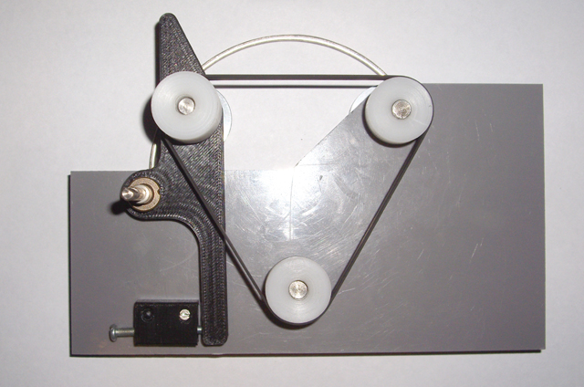
Figure 7. Tension Blocks with Embedded 3 mm Nut
(tolerance-failure included to show nut location)
This experience has given me more insight into improving my OEM plug (see Figure 13). First I need to clean the bed as a matter of course. Second, after the wipe I need to change the 4 mm default rings around the part. If these rings are too small then they will not allow sufficient extrusion to ensure good initial printing. Further, if they fail then they will drag filament across the part printing area. I might be better to have a long zig-zag on one side of the part.
- Clean the bed every time. Window cleaner or methylated spirits and a paper towel works for me.
- For small parts, increase the length of extrusion before the print starts in earnest by adding more apron rings.
For my next project I need a case for my reflow oven controller. This will be my largest print to date with a size of 115 mm x 60 mm x 18 mm. The first attempt failed to adhere adequately to the bed which caused a warped front face and distortion on the sides. The first few layers looked great but I figure that the problem occurred after about the 10th layer. In any case I also managed to get a couple of tolerances wrong for part inserts (some too large and some too small) so I’ll be printing the case again.
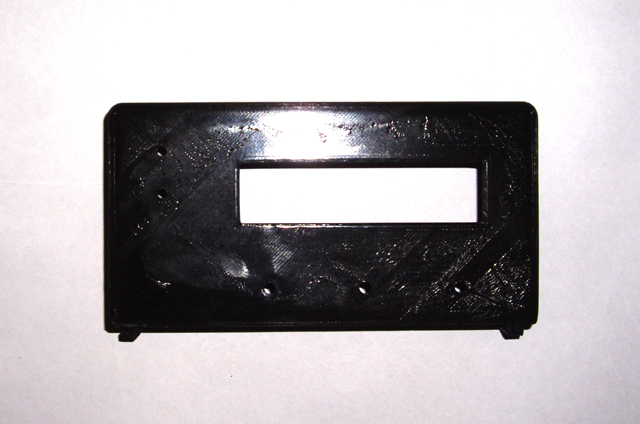
Figure 8. Warped Front
On my second attempt I re-cleaned the bed and tried hair spray. The print was abandoned on the second layer. This is quite frustrating. I re-cleaned the bed with hot water and detergent followed by drying with a paper towel, followed by window cleaner with another paper towel - the glass was squeaky clean. I rechecked the bed levels (all good - although be aware of removing filament ooze before checking the Z Home).
If you are having part adhesion issues to a heated bed then try cleaning the bed with isopropyl alcohol and a lint free paper towel. This works much better than ethanol (methylated spirits) and provides consistent even adhesion. Once the bed has cooled don the part will simply twist off the bed.
- Try using isopropyl alcohol to clean the bed. This results in better hot bed adhesion than ethanol (methylated spirits).
I’m interested to understand the effect of heating the extruder and the bed on levelling. To date I have completed these operations cold (ambient temperature) but stuff tends to expand when it gets hot. If you have any thoughts on this please share them with me.
I increased the pre-print waste to five trips around the part perimeter and reduced the bed temperature from 70°C to 65°C. The third attempt is printing well with no bed separation apparent. At the end of the process the front is glossy smooth with only very minor cosmetic issues. All the part inserts fit like a glove (not OJ’s glove). Whoot!
- Adjust the bed temperature up or down if the bed is clean and your part isn’t adhering. 60 to 65°C works consistently for me with PLA.
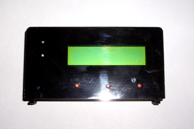
Figure 9. Flat and Glossy Smooth with Parts in Place

Figure 10. Case Internal Detail
There are two more parts to print to complete this case. They are designed but the prints will wait until tomorrow.
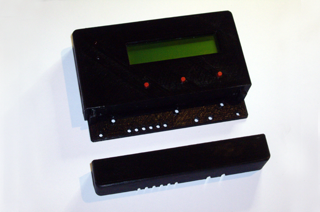
Figure 11. Finished Case
(the terminal block cover fits securely to the case body while allowing ready access)
The case base and front are made and I am very pleased with the results. The front terminal block cover fits securely with the electronics housing. Now I’m waiting on the new PCB to finish the hardware for my improved reflow oven.
I quickly designed and printed a stepper motor mounting bracket for my coil winder experiments. I played with some of the default settings increasing the in-fill and side wall thickness to add strength to the motor mount. The 3 mm holes needed to be cleaned with a drill bit but otherwise a completely acceptable part was conceived, designed and made in about an hour. If I’d set out to make this simple part from and aluminium L section it would have taken at least this long for the machining.

Figure 12. Stepper Motor Bracket
I’m loving this printer to bits, and it won’t be long before I am experimenting with ABS plastic and the 0.25 mm extruder option.
I’ve remade the lever for my coil winder today to incorporate some improvements. While the print is nothing exciting and is probably not even worthy of a photo it did require two attempts. Both parts printed perfectly but the first was a disaster due to me requiring a right-handed part and designing a left handed one. The print has a blind 4.5 mm hole parallel with the X axis. I was very pleased with how well this feature was resolved without requiring support.
- Ensure that your part has the correct handedness during the design.
Another day and another print. Today was the design of a replacement stopper for a hole in a storm water down-pipe. I need to access the hole every month to remove the water from the turtle tank as part of the cleaning process. The old stopper has started to fall to bits and the last thing I need is for it to fall into the down-pipe. The new part was designed in about 30 minutes, printed in 20, and was fitted about 15 minutes later. It is a lot more robust than the previous part and the 3D vertical layering actually enhances the seal.

Figure 13. Downpipe Stopper
I have started on remaking the throttle control handle for my Husqvarna 132R Brush Cutter. This tool owes me nothing after years of use on the farm. It has had a few repairs over time including a replacement engine cowling after the last one caught fire and a few carburettor rebuilds, but the motor and drive shaft are in great shape. The control handle is a plastic component that has become brittle with age. Some months back I inadvertently smashed it into a post and the plastic shattered into bits - some of which were lost in the vegetation. While I was able to effect temporary repairs with Duct Tape these are hardly satisfactory. I tried to order a replacement part but this model is no longer supported. I can’t find an appropriate after-market part and a second-hand replacement is likely to be as brittle as the original.
The print should be straight forward but developing the model from the broken remnants is going to take some time. While I intend to simplify and improve some aspects of the handle for 3D printing, and improve its strength, there are a number of critical dimensions for the trigger, trigger interlock and kill switch that I don’t expect to get these right on the first attempt.
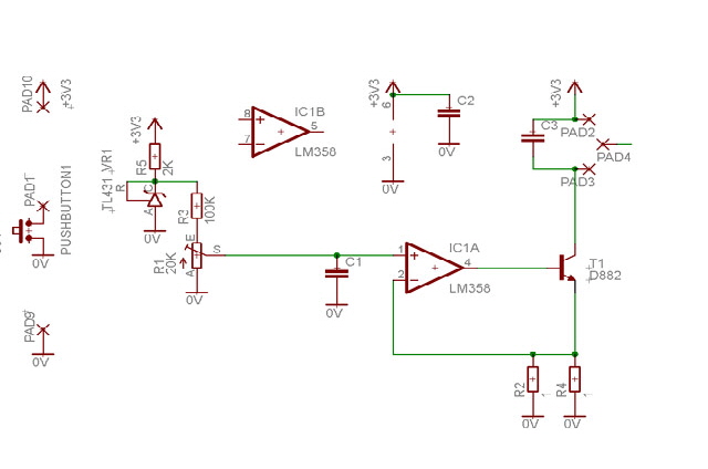
Figure 14. One Section of the Broken Original
(the other half is in much worse order)

Figure 15. Initial Design of Replacement Part
The first print has been completed and, as expected, there a couple of minor modifications required. One boss is too large (the old one was lost so I was guessing here) and the trigger stop is out by about 0.5 mm. There are also some further improvements I can make to improve the case interlocking and strength.
I could cut down on the quantity of plastic considerably but the new part is considerably more robust than the original so I will leave the this aspect of the design alone.
This was my first print onto painters masking tape. I tried this because it promised a more appropriate surface finish for the part. Hand-grips are supposed to provide grip after all.
- After fixing tape to the bed be sure to adjust the Z home position.
- Do not heat the bed with tape applied. The tape will come unstuck and ruin your part.
There were a few problems (learning opportunities) with the print that took six (yes, six) first and second layer prints to resolve. The first problem was that I failed to include support for some of the blind holes. I recognized this at the start of the second layer and abandoned the print. I then went through five attempts where the second layer outline refused to adhere to the first on one area of the print. I progressively checked the bed level and Z home across the print area. I replaced the masking tape. I cleaned the extrusion nozzle. I increased the pre-print apron diameter and number of cycles. But the fault kept on occurring in about the same place on the second layer on every attempt.
- Take time to watch your first few layers print. Aside from being a pleasant and mildly hypnotic experience, if the first few layers are good then chances are your print will be too.
After thinking about what was peculiar to the failure area I came to the conclusion that fillets (radiused corners) were causing low support, and in combination with the profile and increased print speed, causing the extruded filament to pull off the part. The solution that worked for me was to increase the the number of wall layers from two to four. You might also consider reducing the support-to-part clearance, increasing the print resolution, or decreasing the print speed.
- If the outline of a layer is tearing clear of the existing print increase the the number of wall layers and set them to print from inside to out.
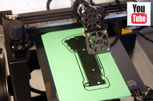
Movie 1. The First Print in Progress

Figure 16. The First Handle Print.
(Internals with lever and trigger fitted. Only two minor dimensional changes are required.)
At the conclusion of the first print the part was stuck fast to the tape and the tape was stuck fast to the bed. With my heated bed prints on glass, the cooled the part comes away with a simple twist but this part was soundly adhered. I tried peeling away the tape and a razor blade with no success. One of my earlier tips advised not to heat the bed with tape because it will loose the tape adhesion. So I heated the bed to 60°C and sure enough the tape came away from the bed and was easily peeled from the part.
- When using masking tape if your print is stuck to the bed then heat the bed at the end of the print.
- When printing on a heated glass bed let the part cool and it should easily twist off.
Tomorrow I hope to complete the design adjustment, reprint this part (both sections) and hopefully reassemble my brush cutter.
As an aside I keep a notebook and camera beside my MakerGear M2 to record significant events and observations. I see that I have almost reached the 10 hour printing mark and it is time for lubricating the Z axis guide rails and lead screw, and the X and Y axis linear bearing rails. I will also check the belt tension. I have another suggestion for MakerGear to improve their product.
The control electronics is quite capable of keeping track of print time and indicating when lubrication is necessary. This could be readily added as a response to the logon script with Proterface. Please consider adding this to the M2 to enhance your product and your customers’ long term experience.
- Keep notes of what worked for you, what didn’t, and what you needed to do to get stuff printing properly.
- Read the printer’s login script. It might tell you something that you need to know.
- Lubricate your printer in accordance with manufacturer’s instructions. This is probably a good time to check belt tension as well.
The new handle parts have been printed and everything fits together and functions. I have some minor sanding to do on the exterior but the new handle is good to go. The new part is significantly more rigid than the old one but this should be fine so long as I avoid bashing the handle into posts.
There are a few minor modifications that I will make to the drawing - two additional fillets, a little more clearance for the on/off switch cables, a little less clearance for the handle recess, and a tad more clearance for the trigger and lever pivots.

Figure 17. The Finished Part
Economy
Time to reflect on the cost of this project. The final part took three solid days to design and a day of printing effort (actually 6 hours of printing including the defective runs). The total mass of PLA consumed was less than 150 grammes; I used a bit of power, processing time, and the equipment and software is always depreciating. The tool that I have saved cost about $1,000 when new and a replacement would be about $1,250 today.
The significant cost of this part is my time. If I were to bill at my standard consultancy rates then I would have saved money by purchasing a new brush cutter. However this project did not compete with my consultancy business. If I charged my time at less than $50 per hour against this project then my efforts have had been profitable. I figure that I am on the right side of the ledger, aside from Green considerations - the alternative was that the brush cutter was destined for the tip.
I can see the day coming where manufacturers don’t have to plan, manufacture and store spare part inventories - and stuff will no longer become obsolete for a lack of spare parts (but there may be other good reasons - such as significant improvements in efficiency in more recent products).
So what’s next on the printing agenda? I still have some reagent bottle caps to print (my first attempt at threads), some serious case prototypes for the Amigo Crew, some complex gearing and assemblies for my terrestrial camera mount, and a laser mount and sensing chamber for my TDLAS experiments.
Woops, after sitting on the bench for two days the base of my brush cutter hand-grip (figure 24) has warped a couple of millimetres. I figure that the problem is the force being applied to clamp the part to the metal arm. As the bulk of the plastic has deformed under compression of the locking bolt, the thin section by the throttle cable has moved in the other direction (just like a see-saw). The original part had a separate external clamp here and now I understand why. I figure that the easiest solution is to interlock the handle halves near at the base and add one or two more bolts to the assembly. I have placed a clamp on the assembled part to gently force it back in shape. After a couple of days it has settled back to a perfect fit implying some creep in the PLA resin. It will be interesting to see if it moves again once the clamp is removed. If it does then I will simply modify the handle design and reprint it. With the clamp removed the part is again distorted by about 2 mm right by where the throttle cable enters the handgrip. I have modified the design but the current part remains completely functional so I’ll be holding off reprinting for now.
Caps and Closures
I have printed some reagent bottle caps and a jar lid. The old ones had become brittle and had cracked. I was expecting problems getting the threads to print but they are a either 45° or half-circular section with course pitches and are self-supporting when printed. The caps and closures function perfectly. I have added a 12 facet exterior to ensure ease of opening and increased wall thickness. These parts were printed at maximum resolution onto a taped cold bed with four external wall layers, and four layers top and bottom. I might try sealing these parts using solvent vapour in due course.

Figure 18. Replacement Jar Lid
(103 mm diameter. Note quick start thread profile.)
A question you might ask is why bother with these prints? Replacement glass reagent bottles (2 litre) are actually not so cheap as to be considered disposable. The jar lid is off an old glass jar that has been around the family for several generations. I understand it used to contain flour but now it is filled with small rocks from the top of various mountains around the world, and a few sea shells picked up on dive adventures (nothing subject to CITIES).

Figure 19. Replacement Reagent Cap with Seal Fitted
(38 mm diameter)
I managed to break the plastic feed stop on my drill press today. I had been drilling some blind holes using the stop. I then set about using the drill press as a press to reassemble my coil winder pulleys. Oops, with the feed stop set the plastic mounting bracket broke as I was pressing a pulley back onto its stub axle.

Figure 20. Broken Stop Feed on Drill Press
Several months back I would still be cursing before spending a day making a new part, but now I have a 3D printer! The model took about 30 minutes to measure up and draw and the print took about an hour and half to complete. There was another learning experience with this print. It has a horizontal recess for a 6 mm hexagonal nut that was printed without support. The layer at the top of the recess failed to print correctly because the span across the flat was too big. So either I should have included support or turned the recess around so that opposing apexes were on the vertical centre line to make a self-supporting structure.
- Print horizontal hexagonal nut inserts with apexes on the vertical so they are self-supporting. Otherwise use support structures.

Figure 21. Replacement Part Printing
The new part fitted perfectly, however it took me a while to remove the drill chuck which hasn’t moved from its Morse Taper since it was fitted about 20 years ago.
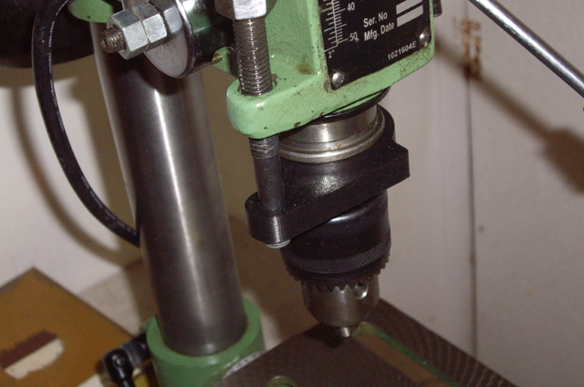
Figure 22. All Back Together and Working Fine
I recently had cause to remove my USB microscope from my PCB drill and use it to inspect some commercial parts for my coil winder. This microscope came without a stand and I ended up improvising a fixture using crocodile clips and a rubber band to get the job done. For very close work this is far from satisfactory as getting to focus dead right required very small height adjustments of the camera. I decided to print a fixture to mount the microscope on the magnetic stand that I use for my Dial Indicator gauge. This stand is robust and has a fine rotational adjustment.
The initial design was a single print with a simple bolt actuated clamp to a 10 mm diameter steel shaft, and a self-clamping USB microscope housing using the plastic housing as a tensional circlip.
I wanted to use a 4 mm nut and bolt for the clamp but I ended up using 6 mm because my stock of 4 and 5 mm bolts weren’t long enough. This is definitely over-kill for this light weight low strength application.
With the first design printed I had a few problems. The hexagonal bolt head recess did not align with the hole (my modelling mistake), the design was missing a degree of movement freedom, and the USB circlip clamp wasn’t as secure as I wanted. I re-designed the fixture as two parts and incorporated some fillets for strength. Here are some design lessons from this part.
- Measure twice, print once! (An extension of the carpenters’ rule which makes it difficult to saw more wood onto a plank.)
- Use fillets and chamfers liberally to assist with mating parts, to add strength, and to prevent stress cracking in sharp corners. While you can 3D print some stuff that you would struggle to make with other processes this doesn’t mean that you can ignore sensible design fundamentals for plastics.
- Getting tolerances right for running and interference fits may take some experimentation. On my M2 the same dimension produces a light press fit and designing 0.5 mm clearance produces a running fit between printed plastics parts. The rules change between printed plastic and metal.
Here is the finished USB fixture. It is functional, stable and secure. There is one dimension that I would change if I were making another one, I cheated by using a 6 mm wing nut as opposed to printing a proper tensioning handle with an embedded nut, and I should fit a 6 mm flat washer under the wing nut.

Figure 23. USB Microscope Mount

Figure 24. USB Microscope Mount
(Rear view. Note the fillet.)
Every month I have a diary entry to clean out Yurtle’s (the turtle’s) tank. This job takes about an hour so everything I can do to speed up the task is worth while. I have a length of garden hose that that get used in the process for refilling the tank from the kitchen. Reeling up the hose by hand is a pain because it’s easy to drop the initial loop and this unravels as the remainder of the hose gets reeled up. The other end is immersed in a full tank and the last thing you want to happen is for the tank to start siphoning out onto the carpet. Even if you don’t have a turtle perhaps you have experienced the problem?
I have designed a simple first-loop clip today that should resolve this problem forever. Here is the drawing followed by the 3D printed part. It fits firmly by the tap adapter and the the first loop is easy to fit and securely retained.

Figure 25. Hose First Loop Clip Design

Figure 26. Hose First-Loop Clip 3D Print
There are no tips as a result of this project because everything went smoothly from concept to final part. However I’ve had a few 3D printing failures over the past month and I’ve been putting the defects out with the recycling. I suspect that I’ll be keeping a few in future for testing of other capabilities including painting, solvent sealing (a method of getting glossy smooth surfaces), gluing, and maybe for experimenting with secondary tooling operations like thread cutting.
- Keep a few of your defects on hand for experimenting with painting, solvent sealing gluing, and tooling operations like thread cutting.
- The world (and its oceans in particular) are becoming a dumping ground for an incredible quantity of plastic. When you throw out your failures use recycling when you can - let’s not add to the problem.
I have re-printed my brush cutter handle today following a re-design to improve the clamping action onto the handle bar and prevent distortion of the case. The clamp is now a separate part but the assembly looks essentially identical to the last one (see Figure 24 above) so I won’t bother with another photo. The clamp is now very secure and there is no case distortion whatsoever. While the trigger works reliably I had to file about 0.5 mm off a boss to ensure that the safety lever would lock in choke (cold starting) mode. There are three aspects to the design that can be improved - the handle bar recess should be increased (back to 16 mm diameter where it was previously), the throttle cable retention can be improved to prevent interference with the safety lever movement, and I want to incorporate additional clearance for the trigger return spring to resolve the choke setting. However the design is working reliably in all modes with no distortion so the immediate job is done and dusted.
So what's next on the print to-do list? I have:
some work to do on the Amigo Crew case to improve the anchor points and streamline the body. The design is almost completed..
a geodesic camera mount for photographing stars. An interesting project involving a worm gear driving a ring gear and some complicated mounts. The design is progressing.
the production test bed for the Amigo (for programing and automated testing).
some simple batten spacers for leveling ceilings (a 15 minute design job).
re-work my plugs (Figure 13) applying what I have learned so far to obtain a better print (and using a finer extrusion nozzle).
a range of new parts for my coil winder development.
my laser mount for my lock in amplifier experiments.
some ideas for circuit board EMI shielding (requiring conductive Zinc paint).
and a heap of other stuff (but no novelties or sasquatches).
Thankfully a consignment of additional PLA and my first reel of ABS has arrived from MakerGear. Along with their complimentary chocolate I have also received a new 0.25 mm extrusion nozzle with the hope of really pushing the resolution of the M2.
Here’s another model that might be of interest to you - a tripod mount for a GoPro Hero 5 Black camera. The model itself is remarkably straight forward, with the camera mount dimensions taken from a standard Hero adhesive mount.
The only trick with this print is to adhere a 1/4” 20 tpi stainless steel nut in the print with super glue to match the mating thread on the tripod. Taping or printing the thread won’t produce a strong mount. The print was completed in PLA at medium resolution. Remember to add support structures for the two mounting rails.
The mount is secure and robust and the camera fits without undue effort.
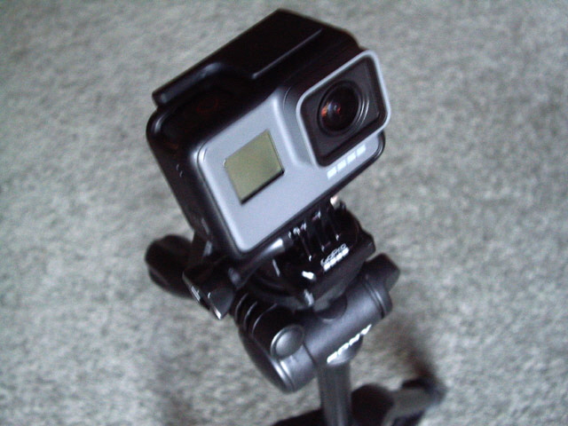
Figure 27. GoPro Hero 5 Black Tripod Mount

Figure 28. Mount Top View
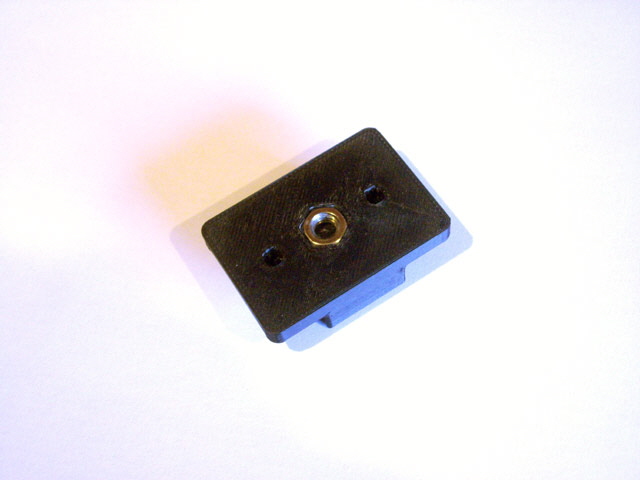
Figure 29. Mount Bottom View with Adhered Nut
You can download the STL file by clicking tripod.ob1. Note that the file name will need to be changed to tripod.stl (the .stl extension causes all manner of grief with file handing in Microsoft Windows due to how it handles thumbnail images). Otherwise click here to navigate to
objects de-art.
|