|
I had a near miss yesterday. The turtle tank pump developed a leak and the spill tray (which was only intended to protect the carpet from minor spills during cleaning) was within a millimetre of overflowing when fortuitously discovered.
This page is about the pump repair, design and construction of a wet sensor, and a cameo on ultra-low quiescent current microcontroller design.
Pump Repair
The external canister filter pump, an Eheim Professional II, Model 2028, is about 15 years old and had a fair bit of maintenance over time. I’ve replaced the primer O ring twice, repaired one of the canister latches, repaired the mains cable to the pump motor stator, replaced a few corroded screws, replaced the media tray gaskets, and replaced the pump impellor. Aside from monthly canister cleaning the pump gets stripped down every year or so, thoroughly cleaned, and lubricated.
I’d rather not buy a replacement because these are expensive. So I set about finding and repairing the leak.
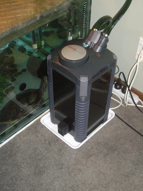
Figure 1. Eheim Professional II Model 2028 Canister Pump and Filter
(Note the new wet sensor in the tray and the new hose clips.)
There are only four possible leak points: the inlet and outlet hose couplings, the outlet sight glass O ring, the canister tank seal, and the primer gasket. The actual leak may be a combination of these sources.
The pump was clearly leaking air into the system, apparent due to pump noise which alerted me to the problem. There was no leakage visible down the outside of the canister but water can flow beneath the corner mouldings. On disassembly the top cover tray was full of water. So the problem wasn’t the canister tank seal. And the primer action was sticky and hard, not returning to the rest position under spring pressure.
I stripped the pump down and cleaned everything, including polishing the primer barrel with metal polish.
The primer gasket was stretched so I replaced it. Thankfully I purchased two the last time this was causing problems. I lubricated the orange O ring and barrel with silicone grease.
I have previously used petroleum jelly (Vaseline) for lubricating the O rings. This is, without doubt, one of my more stupid ideas. Use silicone grease for plastics and rubber. In the first instance Vaseline is too viscose, and in the second instance it may degrade the rubber and/or plastic. I suspect that this may be the primary cause of the leak.
I removed the canister tank seal, cleaned it, lubricated it and re-inserted it upside down to provide a new sealing surface for the tank. I would have replaced it but I don’t have a spare on hand.
There was an accumulation of calcium around the hose couplings. This is a sure sign of leakage over time. I cut back the hoses about an inch to remove the stretched hose, cleaned the inside of the hoses, and refitted them to the coupling using 22 mm stainless steel Jubilee clips. Dipping the hoses in hot water is a great way to soften them for easy insertion over the hose fittings.
Then I cleaned the hose coupling and site glass O rings and tested these with a suck and blow test. There are no leaks here.
On reassembly I found that another canister catch has broken. I’ve already repaired one of these with a piece of Perspex hand fitted and adhered to the existing retainer lugs some years back. I used the same repair technique to re-secure the broken catch.
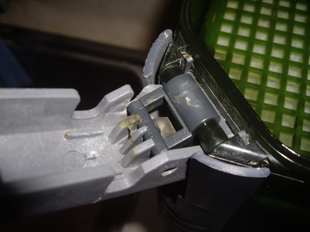
Figure 2. Latch Repair with Perspex Block
The pump is back in action with no leaks after 48 hours of operation, and the primer is working smoothly again.
Wet Sensor
Okay, the pump will live for a few more years, but my main concern is the prospect of emptying 1,000 litres of water onto the floor in the event of another pump failure. I figure that a simple water alarm in the spill tray might be a great accessory to avert a disaster. If the pump fails catastrophically then all is lost as it will empty the tank in less than an hour, and even it isn’t pumping, siphon action will still cause a major flood. But a water alarm should allow me to attend to minor leaks.
The water sense circuit needs to be small, cheap, reliable, stand alone, splash proof, and have exceptional battery life.
Sensing normally-wet is a problem with DC circuitry because sense electrodes can corrode and cause electrolysis at a voltage greater than 1.23 V. But normally-dry can be handled with DC sensing at battery cell voltages without any difficulty. Note that while pure water is actually a very good insulator, the stuff that comes out of a tap isn’t pure, and the stuff in the turtle tank is even less so.
A really simple water sense alarm requires just a single FET, CMOS gate, comparator or op amp driving a piezoelectric sounder and a couple of passive components. With really poor water quality and a low current output indicator such as a efficiency LED we might even be able to dispense with the gain element. I’ve used a Schmitt CMOS inverter in this implementation because the hysteresis should ensure clean non-oscillatory switching between the wet and dry states, and the device has a very low quiescent current.
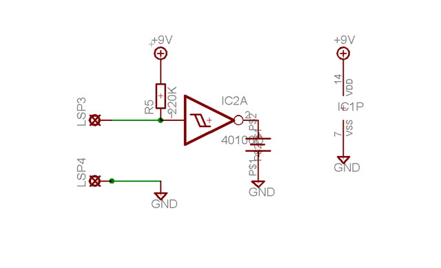
Figure 3. Simple Wet Sensor
The really simple approach has some issues. We can’t tell if the device is operational and the battery is still good without further circuitry. And the piezoelectric sounder must also incorporate an oscillator (an added expense).
However we can do an awful lot with just one CMOS quad dual-input Schmitt NAND gate (CD4093) while still achieving exceptionally low quiescent current. Here is the circuit. It comprises a wet sensor and 0.5 Hz oscillator, an inverter LED driver, and a 4.8 kHz oscillator driving the piezoelectric transducer.
Note that the piezoelectric transducer is effectively driven to twice the rail voltage but there is a DC component when the device is off. This can cause problems with the long term functionality of the device due to metal migration so a DC blocking capacitor (say 33 nF) is probably a good idea. I haven’t incorporated this in the current build.
The LED was really an afterthought and is not really essential. The circuit will operate over a wide range of voltages (say 6 to 18 Volts) although the audio output will be pathetic at low rail voltages. I have incorporated a simple reverse power supply connection protection with a diode. There are better ways of doing this but at increased circuit complexity and cost.
The total cost of parts and a circuit board is estimated to be around $5 for one-off construction.
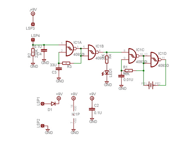
Figure 4. Improved Wet Sensor Design
The circuit is missing some stuff that I’d like to incorporate including:
battery condition monitoring (but the quiescent current should be less than 1 uA so a 9V battery should last for years – close to the shelf-life of the battery).
latching operation.
a two tone or sweep frequency audible alarm.
After designing the wet sense circuit I designed a single-sided SMD circuit board complete with water sense electrodes measuring just 15 x 23 mm (0.6 x 0.9”) but I won’t be making this. I just need a one-off so I’ll revert to through-hole construction using Veroboard. I have a design area of 25 x 50 mm established by the battery profile which should be readily achievable.
Before committing to the final circuit I threw together a matrix board prototype to ensure adequate performance. All of the parts came from stock items - many of them reused from other development circuits.
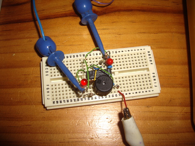
Figure 5. Matrix Board Test
The only component that was hand picked was the ~ 4.8 kHz oscillator resistor. The piezoelectric transducer (muRata PKM13EPYH4000-A0) output is very frequency sensitive, as is auditory sensing by people. Older folk (yeah, I figure I’m in this category) tend to loose their high frequency hearing response. The resistor value was was adjusted to hit the broad peak below 5 kHz in the transducer’s response curve.
This particular transducer is relatively small (about 12 mm in diameter and 6 mm tall) and relatively low cost but there are smaller lower cost options in unpackaged devices. I used this particular device because I have a bunch of them in stock.
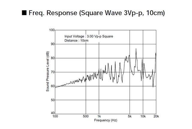
Figure 6. Piezoelectric Transducer Frequency Response
The output tone is pulsed at about 0.5 Hz as this seems to be better discriminated from background noise than a continuous tone. The LED works fine but is not very effective in daylight.
Construction was straight forward and the circuit worked first time. The quiescent current was measured at around 0.4 uA. With the alarm operating it draws about 11 mA (most of this is associated with the LED). The piezoelectric sounder volume isn’t as loud as I’d like but it will be more than adequate to attract attention. An increase in volume will require either a different transducer or a transformer drive to fully utilise the 30 Volt rating.
Other Design Options
Before I actually build the final circuit and put it in a box I’ve thought about all those other nice features that I’d like to incorporate. I can include these using discrete CMOS ICs with just a few additional packages and associated components but the cost, board area, and current consumption are starting to increase significantly.
I considered adapting a smoke alarm IC as a water sensor. The cost was low if I purchased a smoke alarm and pulled it to bits for parts, but this approach requires a circuit board and a fair bit of design and construction effort. The quiescent current for these ICs is typically 10 to 20 uA with a 9 V battery life of over a year.
The most versatile alternative design involves a microprocessor provided that the quiescent current can be kept sufficiently low. Even a modest 8 bit device with ADC capability will replace many discrete logic and analogue integrated circuits at reduced cost and circuit complexity.
Ultra Low Microprocessor Current Cameo
An Atmel ATMega8 in Power Save mode with an external 32.768 kHz asynchronous oscillator we can achieve an average current consumption of about 10 uA. This is good but we are limited to using the internal RC processor clock which must be running at over 120 kHz, is not suitable for precision timing, and we need a watch crystal in circuit.
The longest time interval we can program with a watch crystal for wake up is exactly 8 seconds. With the processor running from the internal RC oscillator at say 8 MHz the processor current will be about 6 mA. If we assume 10,000 cycles for wake-up processing this will take:
10,000 cyc / 8E6 cycles/s = 1.25 ms
The average current will be:
(10 uA x 8 s + 6,000 uA x 0.00125 s) / 8.00125 s ~ 10.9 uA
Note that I’ll be doing this analysis based on average current when what we are really interested in is average power consumption. The advantage of considering current consumption is that is that it is directly measurable with a multimeter.
In the past I have made microprocessor circuits using the watchdog timer to achieve average currents of tens of uA with an 8 MHz crystal clock. In essence the processor is shut down while the watchdog timer times out and forces a reset, but the average current is too high for this application. This design has made me think about how I might reduce the quiescent shut-down current to just a few uA while retaining a crystal controlled processor clock.
I have hit upon the following solution for the ATMega8.
Rather than using the watchdog timer we can charge an external low leakage (tantalum) capacitor to Vcc and use the capacitor and input leakage currents for long time constant discharge (leakage is expected to be around 1 uA). If the capacitor is connected to INT0 or INT1 with a falling edge interrupt enabled the processor will always wake up when the capacitor discharges to about 1 Volt. We can use the same INT pin for charging the capacitor.
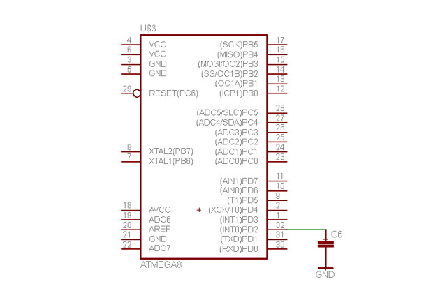
Figure 7. Atmel Ultra Low Quiescent Current
Note that capacitor and IC direct current leakage rates are quite variable and are significantly affected by operating voltage, temperature, and humidity. The sleep timeout period is therefore not accurate and will vary over time.
The capacitor discharge time constant allows an extremely low quiescent current shutdown. On wake-up we test stuff and either go into an alarm condition and stay on, or signal battery condition, recharge the capacitor and go back to sleep.
In power down sleep mode the processor is all but off and the supply current will typically be around 0.25 uA at 25°C (assuming appropriate precautions such as IO configured appropriately). By making the sleep to wakeup time ratio large we can achieve a very low average power consumption.
During every sleep/wakeup cycle we also loose the power used to charge the capacitor so we need to make the capacitor as small as practical. Let’s do some calculations to see what the energy budget is likely to be.
If we use a 10 uF capacitor and assume Vcc is 3.3 V then the capacitor will discharge 2.3 V to the falling edge INT trip point. With an assumed 1 uA constant current leakage this will take about:
Now we need to account for the energy used to charge the capacitor. We’re charging 10 uF by 2.3 V every 23 seconds.
U = ½ x C x V2
= ½ x 10E-6 F x 2.32 V2
= 2.65E-5 J
W = J / s
= 2.65E-5 J / 23 s
= 1.15E-6 W
And with Vcc = 3.3 V this equates to an average current of:
A = W / V
= 1.15E-6 W / 3.3 V
= 0.35 uA
So the average current consumption over a 23 s discharge cycle should be about:
When we wake the processor up it starts drawing appreciable current subject to the clock speed, Vcc and the temperature. Let’s assume that in this application we’re using the 8 MHz internal RC oscillator with a current of about 6 mA and allow 10,000 cycles (1.25 ms) for wake-up processing (as above).
So the average current is now:
(0.6 uA x 23 s + 6,000 uA x 0.00125 s) / 23.00125 s ~ 0.93 uA
This is better than 1/10th of the RTC solution with just an additional capacitor and the dedicated use of an INT port, but the clock pins are now available for a crystal oscillator.
Let’s do the same calculation with an 8 MHz crystal oscillator. There is a slight complication because this takes a recommended 16,000 cycles to stabilize on wake-up (set by the SUL fuse bits) which takes an additional 2 ms at 8 MHz.
The average current consumption increases to:
(0.6 uA x 23 s + 6,000 uA x 0.00325 s) / 23.00325 s ~ 1.5 uA
Of course we aren’t actually doing anything to attract user attention like flashing a battery good status LED. Provided that we keep the duty cycle low (say an 0.1 second 10 mA flash every 60 seconds) then we’ll add about 17 uA to the average current consumption:
10,000 uA x 0.1 s / 60 s ~ 17 uA
There are some limitations with this design approach.
Battery voltage must be appropriate for the processor as a voltage regulator will likely consume as much quiescent current as the processor, and the regulator voltage drop must cause power dissipation which is wasted energy. To avoid a regulator we need a 2.7 to 5.0 V battery voltage. Lower is better for reducing power consumption.
When the processor wakes up it has only an estimate of real time as the sleep time-out interval is not precise (about 23 s in the example above) and we have no internal crystal time-base clocks running during this time. We can overcome this limitation with an external ultra-low current Real Time Clock (RTC) for resynchronisation which will add about 10 uA to the average current and increase the circuit complexity.
With a few other options considered I have decided to simply complete the discrete IC wet sensor build. The matrix board circuit was pretty tidy and small (25 x 28 mm) so I just need to transfer this to Veroboard.
Before starting on the construction I need to think about the case. I can 3D print this to be splash resistant but it won’t be water proof without sealing the printed part. While I could make the sensor buoyant this will increase it’s size because the battery is relatively heavy. So I have decided to mount the wet sensor on the pump canister above the spill tray lip using double sided tape, and with the water sense electrodes extending to the bottom of the spill tray.
Construction was straight forward with the exception of the 33 uF tantalum capacitor which was too tall. I replaced this with a 10 uF SMD device soldered to leads extending from the board and adjusted the associated resistor to maintain the time constant at about 0.5 Hz. I also replaced two other resistors to reduce the board height below the piezoelectric transducer. The board incorporates a single wire jumper on the solder side.
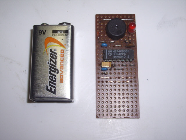
Figure 8. Veroboard Build (Top)
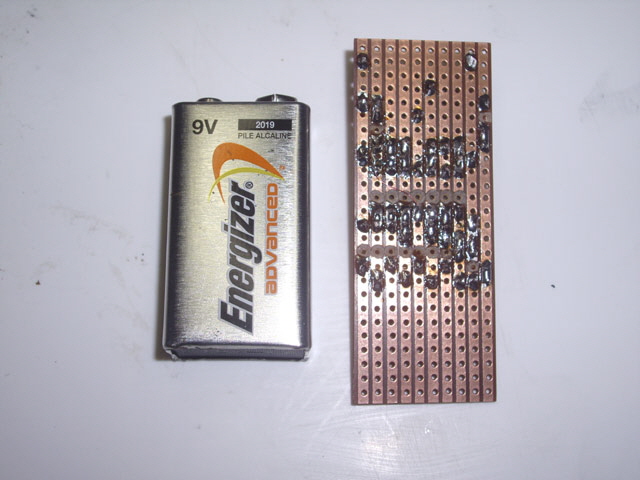
Figure 9. Veroboard Build (Bottom)
The Veroboard build worked first time.
The case was designed starting with a 9 Volt batter holder and mounting the electronics in front. The case should be splash and water run-down resistant. The sensing electrodes extend about 15 mm below the case. The overall case dimensions are 55 mm tall x 37 mm wide x 33 mm thick. There is a slight issue with battery connector as I didn’t leave sufficient side-clearance for it and the 3D print is not perfect, but it will suffice.
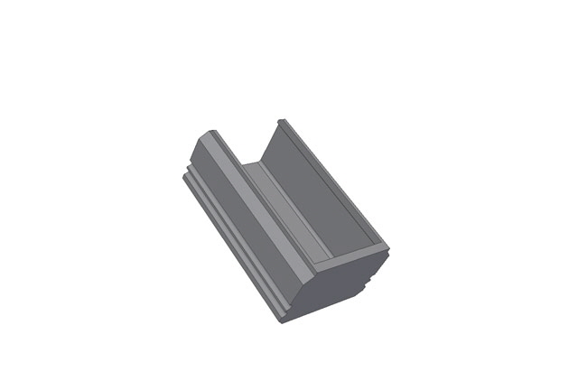
Figure 10. Battery Holder

Figure 11. Splash Shield and Electronics Cover
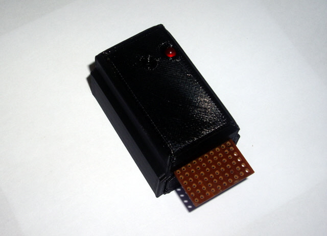
Figure 12. Wet Sensor Assembled (Front View)
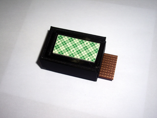
Figure 13. Wet Sensor (Rear View)
The alarm is now assembled and mounted on the pump canister. I’ll test it every month during tank cleaning by simply placing a finger on the sense electrodes.
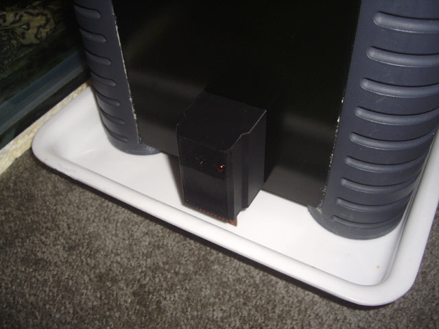
Figure 14. Wet Sensror Mounted and Operational
Job done - well not quite...
A few weeks after I thought this project was done and dusted the pump air leak has reoccurred even though there was no apparent water leakage into the spill tray.
I pressed the primer a few times to purge the air. It had become sticky again. The pump began leaking water into the spill tray and the wet alarm activated. On disassembly the top of the pump was full of water again.
The new primer O ring still looks to be in great order but it was dry with hardly a sign of silicone grease on it. There are no apparent rough spots, pits or scratches in the primer barrel. This is really weird.
While the silicone grease is super slippy it just doesn’t seem to stay where it’s put. I have previously indicated that Vaseline shouldn’t be used for this application but perhaps I got this wrong. Eheim specify Vaseline and actually supply a sachet in their maintenance items. Maybe I need to revisit the lubricant issue?
I reassembled the pump but after a few days later the spill alarm alerted me to another slow leak into the tray. I’m going to pull the pump down again, clean everything, and try and find the leak again.
The pump is still bleeding air and on priming it is leaking water into the top of the pump housing. The primer O ring is now lubricated with Vaseline and has retained a smooth action. There is no water cascading down the outside of the canister so I doubt that the leak is between the pump head and canister seal. One area that I haven’t focused on to date are the O ring connections between the hose connector block and the pump (the hoses are absolutely secure with the new hose clamps).
I removed the hose attachment fitting O rings and sure enough they have become distorted over time, probably because these fittings carry the weight of the water filled hoses. I’ll need to be doing something about this.
After some more thought I have come to the conclusion that the air leak into the canister must be through the intake hose coupling O ring and/or the canister gasket. These are on the suction side of the pump so water leakage shouldn’t occur here under normal pump operation. The outlet hose coupling can’t be bleeding air because it is pressurized by the pump. It may be leaking water into the top tray, but if this is occurring it is very slow.
When the pump is primed to remove air, the primer piston action combined with pumping causes the canister to pressurize causing water leakage out of the hose fitting O rings into the pump top housing. This leakage can’t be from the canister gasket because it can’t leak up-hill into the pump top housing and there is no sign of leakage down the outside walls of the canister. Eventually the top housing becomes full and now we have a leak into the spill tray
I need some replacement hose fitting O rings and while I’m about it I’ll get a new canister seal gasket and a spare primer O ring. While these are relatively expensive they are a far cheaper option that a new pump given that everything else is serviceable (which it appears to be).
The new seals have arrived and been fitted. Yurtle’s pump has been back in action for over a week with no leakage whatsoever. During the first 24 hours there was some air build-up in the pump but I figure this was air trapped in the canister filters gradually making its way to the top of the canister. This was readily cleared with the primer.
Hopefully were finally done, but the wet alarm remains in place to provide early warning of any leakage into the spill tray.
|