|
I am confident from my earlier experiments that I can weld secure battery tabs, but for making battery packs (with 2 to 4 welds per cell and up to 15 cells) I need to have a repeatable process for every weld.
The pulse parameters of my dual pulse capacitive discharge welder can be set with appropriate precision and repeatability. However hand held electrodes are not ideal for a repeatable process. While my welder is triggered by a foot operated switch, both hands are required to hold the electrodes in place, maintain alignment of the tab, electrodes and battery, and apply constant and repeatable pressure. This is somewhat taxing, not helped by the natural tendency to blink and flinch during the current discharge pulses.
Commercial welders use a weld head to position the electrodes and apply pressure, providing relatively constant mechanical weld conditions. I really need one of these for making battery packs. I have several vertical mechanical drives in the shed including a mill, a drill press and a Dremel press. Surely I can improvise a weld head for one of these. Let’s give the Dremel press a go.
The weld head design is based on the Dremel tool holder dimensions. Fabricating the tool head in metal would provide very robust construction but with insulation issues that would require insulating sleeves, spacers and washers. The original Dremel tool holder is moulded in plastic so maybe I can 3D print an appropriately rigid weld head?
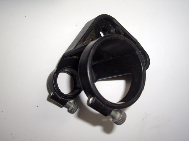
Figure 1. Original Dremel Holder
The weld head concept is quite straight forward. The electrode holder is driven vertically downward by the Dremel press. Electrode pressure is provided independently to each electrode by steel compression springs. The maximum compression is set by the Dremel stop. The spacing between the electrodes can be varied from about 0.5 mm to more than 50 mm by simply rotating the electrodes.
I’ll be using scrap hardware where I can including an 8 mm diameter steel rod and bronze bearings that were recovered from an old printer and some springs that I have salvaged from some junk.
The design requires a bit of machining for the electrode holders including a few holes to drill and tap, a couple of external threads to make with a die, and a precision slit to form the electrode clamp.
The process started with designing and 3D printing the Dremel press adaptor. I put some effort in to ensuring the part would be robust to minimise deflections caused by the electrode pressure. This was quite a large 3D print taking over four hours at medium resolution largely due to the amount of infill required to support the part. The first effort looked just fine and had plenty of rigidity, but there were two critical dimensional errors (my dumb).
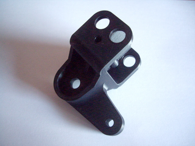
Figure 2. Initial 3D Print
(Complete with dimension errors.)
On the basis of the first print there are a few other design improvements that I can implement. My original concept used 16 mm diameter copper rods for the electrode holders but a rectangular section will be more versatile, allowing for tungsten electrodes and a reduction in the inter-electrode distance. This will also reduce some dimensions on the Dremel bracket making it more robust and quicker to print. The down side is that I will need to machine some rectangular section copper.
The model was adjusted and the 3D print was started but aborted early due to lack of adequate support structures for acute angles on large diameter fillets. This was followed by all manner of 3D printer problems associated with extruder issues. You can read about these by clicking here.
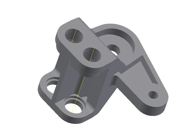
Figure 2. Adjusted Dremel Adaptor Design
With the printer now back in service and printing reliably I set about printing the new Dremel bracket and the bosses. This aspect of the weld head is a complete success. The head applies an adjustable and repeatable 2 to 15 kg (about 4 to 33 lb) to the electrodes (measured with a spring scale).
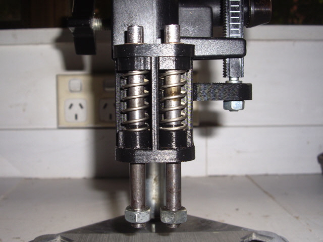
Figure 3. Dremel Adaptor Done and Dusted
Now I need to complete the detailed design the electrode holders. For good conduction I’m going to use copper as the base material. For easy adjustment I’ve settled on a circular electrode clamp. The connection to the press is an M8 thread. The biggest challenge will be attaching the 0 AWG welder cables to the electrode holders. I figure on using a copper lug machined from 16 mm diameter copper rod and attached by a 6 mm diameter bolt.

Figure 4. Electrode Holder Design
The original battery pack welds were made with two weld pairs per battery electrode (four individual welded connections each 1 mm in diameter and about 3 mm apart). The weld head electrode pressure was sufficient to clearly indent the nickel tab.
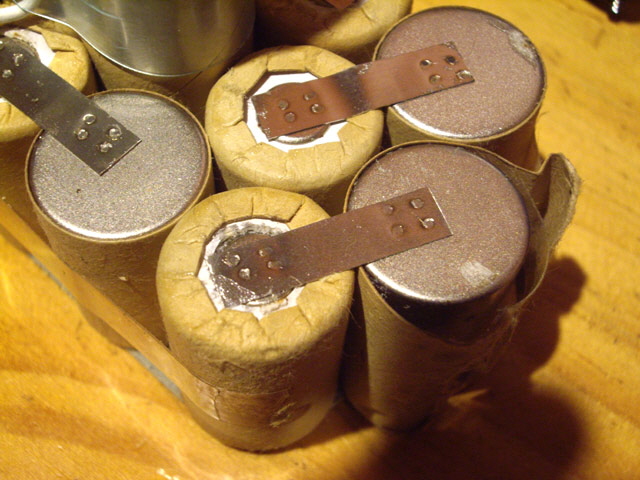
Figure 5. Original Battery Pack Welds
(Each weld is approximately 1 mm in diameter)
My nickel strips are 6.35 mm (¼”) wide and 0.14 mm thick. The conduction cross section of the nickel is therefore 0.89 square mm. The distance between a positive and negative battery electrode is about 15 mm. The electrical resistivity of pure nickel is about 7E-8 Ohm m. The resistance of each tab is therefore around 0.1E-3 Ohms.
Provided that we have a welded connection area somewhat greater than the nickel strip cross section this then the welds will not contribute significantly to the battery pack resistance. A pair of 1 mm diameter welds has a maximum conductive area of 1.57 mm2. A pair of 2.4 mm welds will have a maximum conductive area of 9 mm2.
I figure on using 2.4 mm diameter electrodes because I can readily replace these with standard dimension tungsten rods for welding copper and copper alloys. I can easily get two weld pairs on the smaller positive battery terminal within the confines of the nickel strip. If necessary I can adjust the electrode tip to make a smaller weld diameter.
With 2.4 mm diameter electrodes the maximum weld pressure with my Dremel jig is about
This is somewhat greater than a ton per square inch (tsi). If I reduce the electrode tip diameter to 1 mm the maximum pressure will increase by a factor of almost six!
Now to machine the electrode holders...
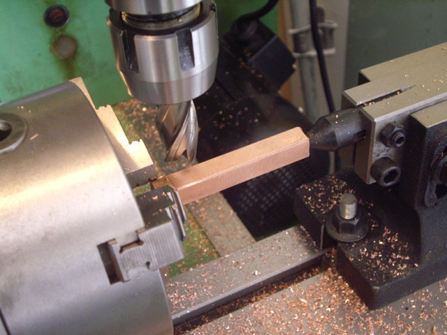
Figure 5. Milling 12 mm Square Section Copper from Rod
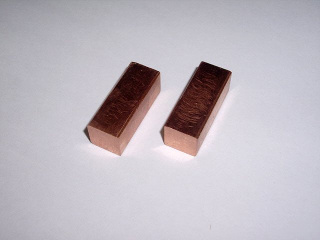
Figure 6. Completed Blanks for Electrode Holders
I managed to almost finish machining the electrode holders today. Unfortunately my narrowest slitting saw is too wide (1.5 mm) for this job. I have some 0.5 mm and 1.0 mm saws on order. But apart from the slots, the holders are done. I have fitted them to the Dremel bracket. Otherwise the action is pretty good. Adjustment of the inter-electrode spacing works fine and the electrode holders maintain their alignment when the compression springs are loaded. I need to chamfer or fillet the closest electrode holder corners to minimise the inter-electrode spacing, but not until the slots are cut.
One of the rod threads is slightly drunk so this rod will need to be remade. This is a consequence of die cutting a male thread by eye. While taps tend to self-centre, dies don’t. If your thread is even slightly drunk cutting will be hard work. The die needs to be kept square using a drill press or a lathe tail stock while initiating the cut. The new rod was cut using the appropriate procedure and this problem has been resolved.
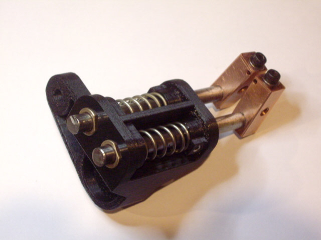
Figure 7. Electrode Holders All But Complete
(Slots still need to be cut through the electrode recesses.)
Making the 2.4 mm diameter electrode holes 0.5 mm from the edge of the copper was a bit of a challenge. My first attempt almost ruined the blank so I experimented with some scrap copper to find a process that would work. I managed to break two 1.2 mm drill bits during the experiments as copper is quite ductile and tends to stick and bind to the tool. The final process used the Dremel press to drill 1.2 mm pilot holes at about 10,000 RPM using a very slow hand feed and cutting oil. Then I progressively drilled these to size on the mill at 660 RPM, again with hand feed so I could feel for any problems, with a very slow feed rate, lubricant, and with frequent partial backing out. The thin wall was reinforced in the mill with a piece of scrap steel clamped tight in a machine vice but the copper wall still distorted slightly. This was filed back to flat. In retrospect I should have drilled these holes part-way through making the blanks and milled the blanks to size. I can see why the commercial electrode holders use a simple Vee notch and plate to secure the electrodes. However my arrangement should provide a much lower discharge path resistance because the electrodes should have greater than 85% (78 mm2) of the available contact area.
I may need to increase the electrode hole size to 2.5 mm if there are any issues inserting the electrodes. As a late thought there is scope to incorporate a plastic spacer between the electrode clamping bolts should this be necessary.
While I’m waiting for the slitting saws to arrive I can make two 0 AWG cable terminations that will bolt to the electrode holders with M6 x 1.0 bolts, make some 2.4 mm diameter copper electrodes, make sure that the welder is still functional (it has been packed away for well over a year), and maybe finally get around to putting it in a case.
My welder was dusted off and worked perfectly first time with no work other than a quick vacuum clean. The capacitors are still at about 3 Farads and hold charge, and nothing is getting hot.
I replaced the missing temperature sensors on the charge/discharge board and MOSFET switch heat sink. The new sensors have an improved cable mount to prevent flexing of the LM335 leads; the cause of the original failure. They work well.
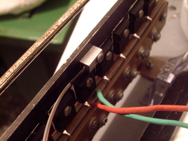
Figure 8. New LM335 Temperature Sensor
In order to make progress with the case I moved the main bus, capacitors, power transformer and chare/discharge heat sink towards the back of the case by 25 mm. While the original design had adequate clearance, the addition of the free wheeling Schottky diode and transils on the bus pretty much used this space up. The microprocessor and discharge board mounting also need to be improved. While the double sided tape has worked for about six years this was never intended to be the long term arrangement. The original metal bracket is also rubbish cut from a barely adequate piece of scrap. I have thrown it out and will be making a lighter, stronger one.
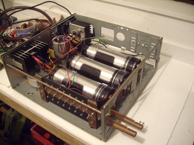
Figure 9. Bus Cleared From Front of Case
(Note removal of the MCU board and bracket.)
Today I have remounted the electronics and put a case front on the chassis. The boards are attached by 3 mm bolts that screw into the Perspex plate for ease of assembly and servicing. I’ll be mounting the Perspex on four 90 mm long 6.35 mm diameter aluminium stand-offs mounted between the capacitors.
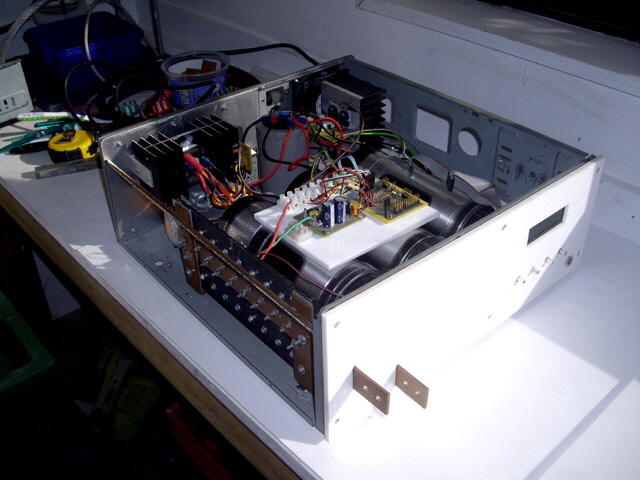
Figure 10. Front Panel and Electronics Board
The stand-offs have been made and fitted. The only thing left to do with the welder to get it operational again is to reconnect the electronics sub-assembly with pretty much everything. The connections are made by headers and plugs and terminal blocks so shouldn’t take too long. There are a few leads that I want to shorten and at least one that needs lengthening (the ground on the foot-switch socket needs to connect to the single point ground on the chassis). Of course it still needs a case and I’ll be getting on to this shortly, but I don’t have a box and pan bender or a guillotine big enough for this job.
The welder is fully connected and operational again and I have machine a couple of 19.40 mm long 2.4 +0.02 -0.05 mm diameter copper electrodes from scrap off-cuts. This was quite a challenge as the small work is relatively flexible and tended to flex away from the cutting tool. There is no room here for a steady and job was machined from a three jaw chuck without using a tail stock centre.
There is not a lot left to do before I can start testing the welder on battery pack tabs (and I have a lot of dead batteries for these tests.) Just some terminal blocks for the 0 AWG cables and 0.5 mm slitting of the electrode blocks. I’ve decided to solder the terminal blocks to the cables as this will provide a better (lower resistance and less weight) connection than the previous purely mechanical cable clamps.
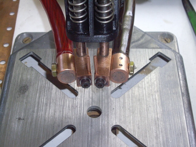
Figure 11. Soldered Cable Terminal Blocks Bolted to Weld Head
The Dremel support column is a 1” diameter steel tube and placing this between the welder cables is probably not a good idea. It will act like a shorted turn, get hot, and waste energy that we want applied to the weld junction. The cables are sufficiently flexible for routing both on one side of the Dremel column.
The weld head handles the cable weight nicely. I had intended to 3D print a cable support but maybe these are not required? Only the slitting of the electrode blocks is required to finish the weld head and start experimenting with battery tab welds.
I’m still waiting for my slitting saws so in the interim I have finally got around to making a case for my welder. This has only taken six years! I don’t have any serious sheet metal equipment (just aeronautical tin snips, a hammer, a vice, pliers, a home-made folder and a collection of files) but the case will be quite functional and it will certainly keep the dust out. The case is 0.8 mm thick steel from a backing sheet of some old steel shelving.
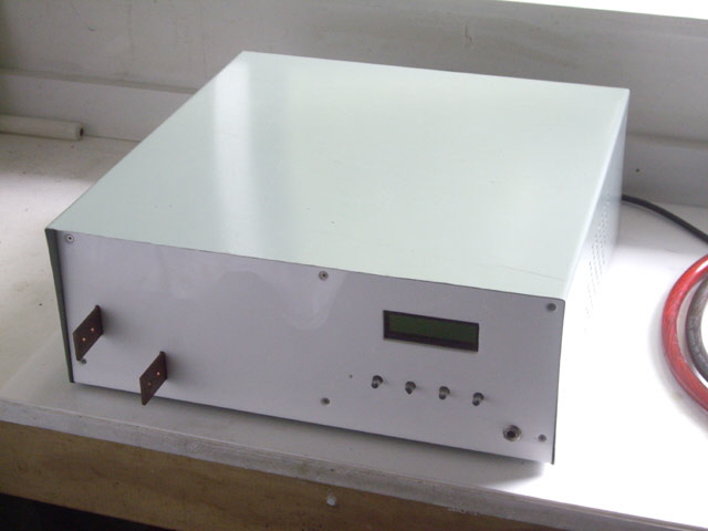
Figure 12. The Welder Finally in a Case
The welder pulses are actuated by a foot switch which is probably not as convenient as a push button control on the Dremel press lever arm. Unfortunately my 3D printer is waiting for some parts so I can’t be making this immediately but I shall be getting on with the design. With the welder connected there is somewhat more tension in the 0 AWG weld cables so I have also decided to make up that 0 AWG cable guide after all.
The race is on to see what arrives first: my printer parts or slitting saws.
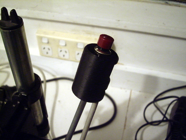
Figure 13. New Weld Head Discharge Trigger on Press Arm
Have 3D printer parts but no slitting saws. I’ve printed out the discharge trigger and mounted it on the Dremel press arm. The switch isn’t the smallest one that I could have used but it’s really solid and requires a positive thumb press to activate. The cable is also way to large for this duty but it was quicker to remove the old foot switch and use its cable which is a shielded twisted pair. I’ll attach the cable to the press arm with couple of cable ties in due course. Guess I’ll be getting on with the weld cable guide.
They’ve arrived! Before cutting the adjustment slots I had to attend to a minor issue with vibration in the milling head. The problem was that one of the pulley grub screws had worked loose. It took some time to find but was easily fixed.
I machined the 0.5 mm wide slots at the low end of the recommended cutting speed for copper using multiple 2 mm deep cut upward milling. Then I over drilled to the outer leaf adjustment hole to 4.2 mm with the shank of a 2.4 mm drill bit in the electrode hole as a spacer, and hand filed the leading corner chamfer. I also ran a 2.5 mm diameter drill bit through the electrode holes by hand to give them just a little more clearance. The electrode clamping is rock solid and everything is readily adjustable. The electrode holders need a good clean but otherwise the weld head is pretty much done. I’ll apply some adhesive tape or thin plastic between the electrode blocks to ensure that these cannot short.
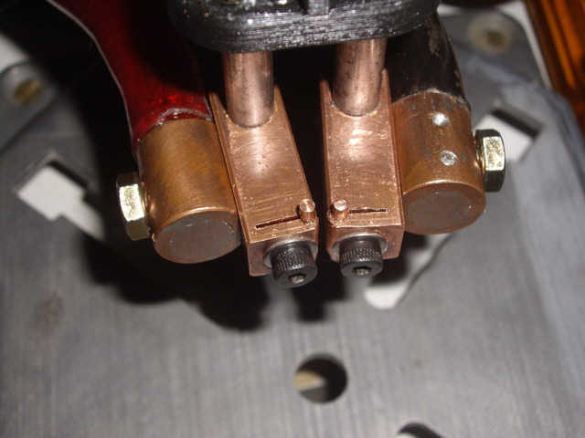
Figure 14. Weld Head Completed
Tomorrow I can get on with trying out the weld head and adjusting the welder parameters to make repeatable reliable battery tab welds.
The new weld head works well although it does creep forward about 2 mm during application of weld pressure. This is a consequence of the torque being applied between the tip of the electrodes and the point where the 3D printed part is bolted to the Dremel press shaft (forming a 50 mm lever). I have placed a slotted steel seating washer on the shaft to provide additional support for the 3D printed part. This has reduced but not entirely eliminated the electrode movement.
Click here to see a video of the new weld head in action.
Click here to read about rebuilding battery packs...
|