|
Turning stopped-threads on my lathe can be a bit challenging because there is no carriage stop and the minimum chuck speed is 160 RPM (almost three turns a second). For relatively fine pitch metric threads (say 1 mm or less) I usually revert to turning the chuck over by hand and making light cuts. Left hand turning with the tool at the back of the stock also works, but a better approach is to slow down the chuck and incorporate a carriage stop.
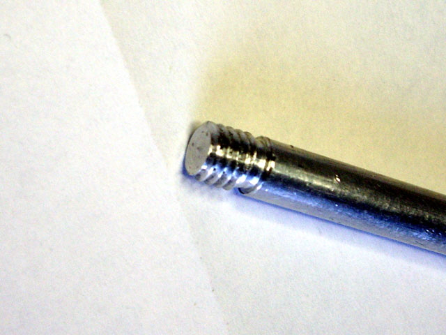
Figure 1. Short Stopped Thread in 6 mm Diameter Silver Steel
The easiest way to implement both of these functions is with a Variable Frequency Drive (VFD) which allows the motor speed to be reduced and provides low voltage digital inputs for controlling the VFD output.
The 0.75 kW lathe spindle motor is has a name plate speed of 1400 RPM at 50 Hz so this is a four pole motor. With a VFD we can decrease the motor speed below 280 RPM (and we can increase it above 1400 RPM if desired, although there are good reasons why we might not want to do this).
Modern VFDs are relatively small, robust and reliable, and they need not be expensive. I purchased a
V2-2R2G-S2 Chinese manufactured single phase 230 V, 50 Hz, 2.2 kW VFD for about US$60. It is just 150 mm high x 115 mm wide x 150 mm deep.
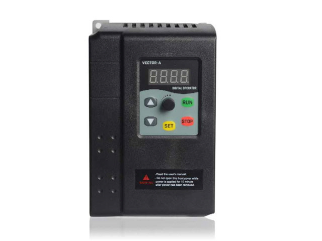
Figure 2. Varable Frequency Drive (VFD)
Model V2-2R2G-S2
The unit arrived after a few weeks but it had been damaged in transit. The double wall carton had clearly taken a significant hit, the plastic case was crushed and split, and something was rattling around on the inside. Bugger!
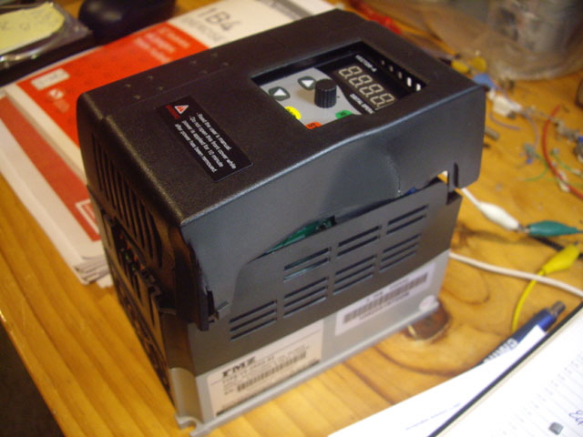
Figure 3. VFD Severely Damaged in Transit
After negotiations with the supplier I agreed to inspect the unit and test it. Removing the damaged case was straight forward. Two of the case mounting screws were severely bent (probably caused by the impact) and their threaded holes will need some rework.
I was dreading that the rattling was a broken component but it turned out to be a broken piece of plastic from the case.
The printed circuit boards all look to be serviceable without any cracks. All of the components looked serviceable although the output screw terminal block had been bent sideways. A quick tweak with some pliers and it was back in position.
The heat sink and fan were in good order (except for the threaded holes for case mounting). I ran an M3 tap through these to reform and straighten the thread.
Testing the VFD without the covers is potentially hazardous because the rectified mains is at 340 VDC with a substantial filter capacitor. There is enough energy here to cause severe electric shock hazards or electrocution (the latter meaning death). Note the warning on the (broken) cover that states:
Clearly I need to apply power for at least 10 minutes before removing the covers... NOT. I suspect that what they meant to say is ‘Disconnect power and wait 10 minutes before removing covers.’
First up I did a few quick Ohmmeter tests on the unpowered unit to establish grounding and look for phase and neutral shorts to ground. All good here. The case mounting screws actually establish Protective Earth (PE) grounding of the heat sink and the original machine screws were too long without the case. I found some shorter M3 machine screws (about 10 mm) and re-established PE to the heat sink.
The plastic case also secures the digital control panel. I placed a piece of 3 mm thick Perspex under the panel to partially secure it and prevent me from accidentally putting my fingers somewhere truly dangerous.
With power applied everything appears to be working appropriately. I set about changing a few parameters starting with changing to digital input (F1.15 - the potentiometer is too sensitive for accurate frequency setting), turning off the deceleration time to 0.1 s minimum (F0.11 - originally set to 2.5 s), and adjusting the motor parameters (F4-00 to 05) to suit my candidate test load.
Now for the test load. I don’t want to unwire the lathe spindle motor just yet, but I have an old ¼ HP two pole induction motor that has been sitting in the garden shed for 17 years!
The name plate speed is 2850 RPM. The motor is actually the drive for my shearing plate cutter grinder from the days when I had a farm and used to shear sheep. The motor has accumulated a bit of rust on the shaft and case but the spindle turns freely, the wiring looks to be in good order. The motor is pretty much sealed so it should still work. Ohmmeter tests proved that the insulation resistance is good (greater than 30 Meg Ohms) and the case is earthed. I clamped the motor to a bench, lubricated the bearings and powered it up. It ran straight up to speed just fine with no vibration, and just an occasional very brief crunch noise which needs to be investigated. After a few minutes of running the case was hot to the touch but the bearings were just above ambient temperature. Induction motors can run too hot to touch (say > 40°C) and this isn’t a problem provided that the winding insulation thermal rating isn’t exceeded.
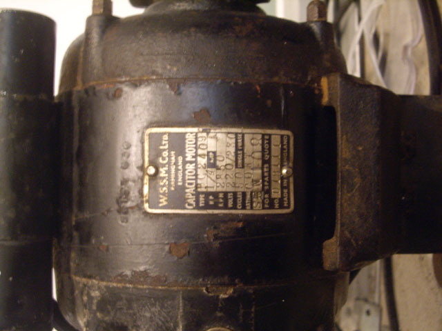
Now, time to investigate that crunching noise. The only way to do this is to disassemble the motor taking care not to damage the stator windings. With the four tie rods removed the cast aluminium end plates separated from the stator body with just a bit of leverage. The pole faces on the rotor and stator are clean and clear, there is nothing rattling around inside, and the windings are secure and look to be good order.
There is a centrifugal switch that disconnects the start capacitor at about 2,500 RPM. The switch has mechanical hysteresis and re-connects at around 1,700 RPM. This must be the source of the crunching noise. I removed and cleaned the springs with a brass wire brush, cleaned the rest of the switch a toothbrush with isopropyl alcohol followed by very light lubrication of the axles and springs. I also ran a points file across the switch contacts.
The face of the rotor housing looks like it has been crushed by a tool some time in the past. I’ve never had this motor apart before so someone else is responsible for this abuse your Honor. While I could attempt to repair this, it appears to be largely cosmetic (maybe causing minor rotor imbalance).
I cleaned up the terminal board with a toothbrush and isopropyl alcohol.
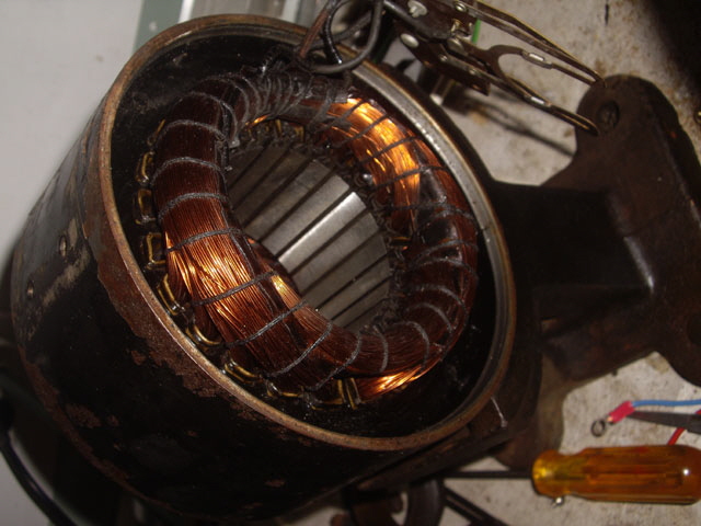
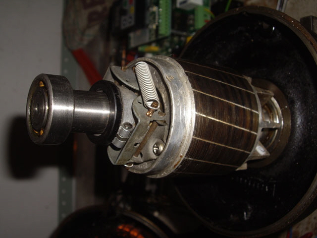
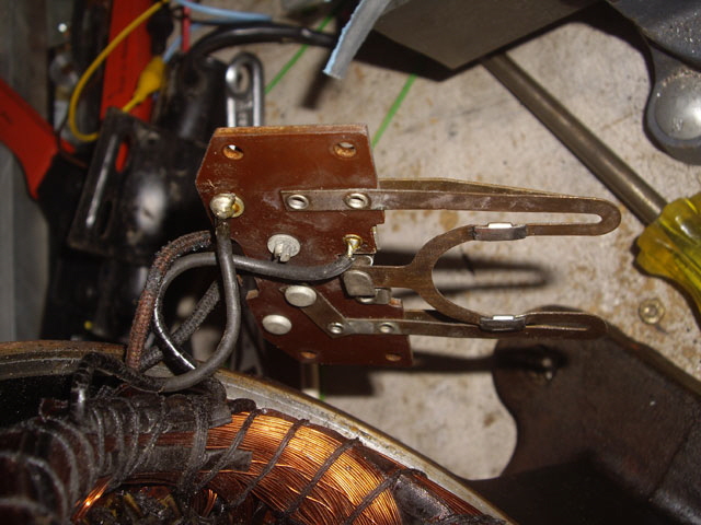
The motor was reassembled taking care to prevent any damage to the windings and avoiding the use of undue force. The bearings aligned perfectly and the rotor turns freely by hand. The bearings were re-lubricated with molybdenum grease. Don’t use oil for this as it will simply run out, possibly ending up on the windings which can get hot.
After further Ohmmeter checks power was re-applied. The crunching noise has gone and the centrifugal switch is clearly working now (I can see a light spark as the contacts open).
We have a test load! This is testament to how rugged induction motors are.
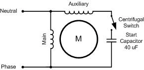
We have a single phase split pole capacitor start induction motor, and three phases (U, V and W) at the VFD output. The capacitor on these motors is specifically designed to produce a 90 degree phase change in the auxiliary winding from the main winding at the rated frequency (50 Hz). This is necessary to produce a rotating magnetic field otherwise the motor will not start.
A question you might ask is what happens with the motor terminal voltage when running between two phases of a 3 phase VFD? The answer is that it will be about 85% of the VFD single phase supply. In order to understand this we need to think about what the VFD is doing.
The incoming nominal 230 VRMS 50 Hz AC single phase supply is bridge rectified and filtered to produce about 325 DC (230 x sqrt(2)). This is then converted to three phase simulated sinusoidal voltage at the desired frequency by the VFD with a maximum voltage of 325 Vppk. So the RMS output voltage of any one of the phases referenced to a notional neutral is about 115 V RMS (325 / (2 * sqrt(2)). And the voltage between any two phases will also be sinusoidal with the same VFD output frequency at 200 V RMS. We can simplify the maths between each of these steps:
In reality the output will not actually be a true sinusoid and the peak voltage will be slightly lower due to semiconductor losses. Voltmeter measurements between the VFD phases shows that the phase-to-phase output RMS voltage is almost equal to the single phase input RMS voltage (230 V RMS). The reason for this apparent anomaly is the VFD simulated sine wave is not truly sinusoidal.
There are two possible ways of connecting a single phase capacitor start induction motor to the three phase VFD output (U, V, W). Before messing with the wiring I photographed the original so I can restore the motor connections at the end of my experiments.
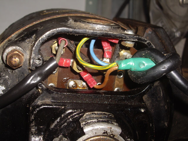
Figure 9. Original Wiring
The easiest configuration is to simply connect the single phase motor between any two of U, V and W, leaving the motor start capacitor as originally wired. But single phase induction motors are designed to operate at a particular frequency (in this case 50 Hz) and that the start capacitor will remain connected at low RPM. The motor’s characteristics will change as the frequency varies, and at low frequencies and we can expect low starting torque due to the capacitive reactance (several thousand Ohms) resulting in a significant reduction in the auxiliary winding current.
A better approach is to connect the main motor winding between any of U, V and W, remove the motor start capacitor, and connect the third phase to the free terminal of the auxiliary winding. The phase difference between the primary and auxiliary windings required for starting is now provided by the VFD for all frequencies and the auxiliary winding current is no longer limited by the capacitive reactance at low frequencies. The motor direction can be changed by swapping the two phases connected to the main winding.
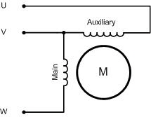
Figure 11. Three Phase Motor Wiring Schematic
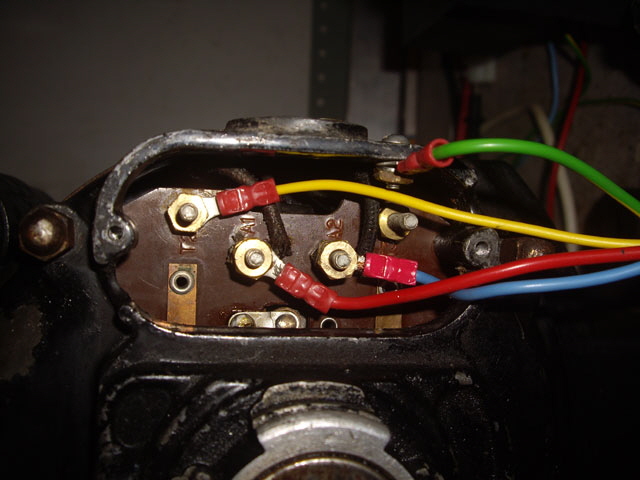
Figure 12. Wiring Modified
I’d like to model the motor before applying power through the VFD but this is not a trivial exercise. The two stator windings couple to the rotor as transformers, with a degree of mutual coupling between the two. Unlike a transformer, where the rate of change of the flux in the core is dictated by the frequency of the primary supply, the rate of change of the flux is governed by the difference in rotational speed between the rotor and the rotating stator magnetic field. This is further complicated by potential saturation of the stator core and mechanical loading so I won’t be modeling this.
With an AC ammeter attached to the VFD supply to monitor for over-current, and the motor wired to the VFD I powered it all up. We have frequency control with reasonable torque, even at at low frequencies. The motor will start right down to 1 Hz although the torque is very lumpy at such a low frequency. Interestingly the motor casing is appreciably cooler than prior to servicing and connection to the VFD. The motor case is just above ambient (just warm to touch) after a significant run time at various speeds.
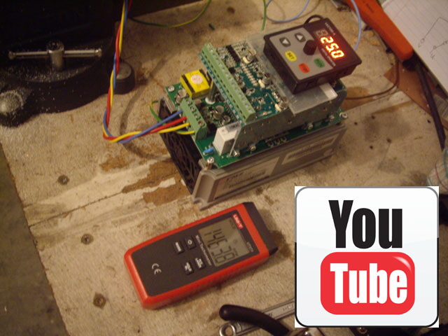
Figure 13. Motor Speed Control with VFD
The VFD manufacturer has sent some new plastic cases so I’m waiting for these to arrive before I can fit the VFD to my lathe spindle motor. After a few communication issues and Covid-19 delays I have a new two piece plastic case for the VFD. The first package only had the top when I requested when a new top and base. After a further email exchange and another delay a second package arrived with a new plastic case complete. So I have ended up with a spare plastic top. My thanks to Peter at SHANGHAI FMZ INDUSTRY CO., LTD for great service.
Fitting the case should have been straight forward but there are three aspects of the VFD design that I am not thrilled about. On fitting the case the heat sink wasn’t connected to Protective Earth (PE), and the output filter ground connection isn’t great. The problem is that these connections rely on compression of the PCB against the mounting studs by the case machine screws. The PE connection in particular is not helped by the board corner cutout for the case.
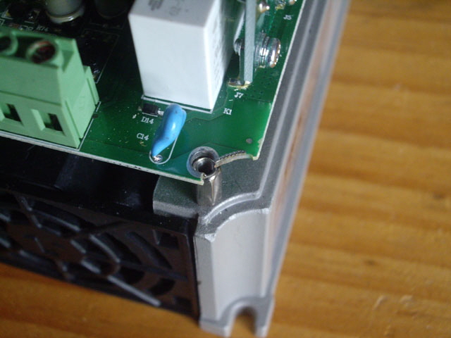
Figure 14. Weak Protective Earth Connection to Heat Sink
I fitted two Nickel plates to ensure a positive connection under case compression. These ensure that both the upper and lower PCB lands are connected to the mounting studs under compression. The connections have a reliable resistance of less than 1 Ohm.
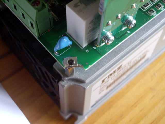
Figure 15. Nickel Tap to Improve PE Connection to Heat Sink
The second issue was the mounting of the digital control panel which is not rock solid as supplied. I fitted a strip of double sided tape between the panel and the base so the panel it is absolutely secure.
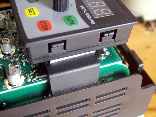
Figure 15. Double Sided Tape Support for Control Panel
With the modifications complete the case and controls are secure, and the heat sink and output filter ground are reliably connected to PE. The unit was tested again with my ancient induction motor and we’re good to go.
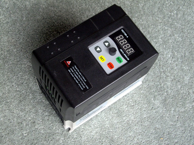
Figure 16. VFD Ready for Installation on my Lathe
Now all I need to do is sort out where to mount the VFD on my lathe, adjusting the wiring to retain motor reversal, and implement a carriage stop.
More to follow...
|