|
My hobby CNC mill came with three A4988 stepper motor shields. A potentially useful and low cost upgrade for the mill is to change these out for Trinamic Motion Control shields based on the TMC2208 integrated circuit. These are available from DigiKey for just a few dollars and will apparently make the stepper motors silent, improve the micro stepping resolution, and maybe allow me to introduce zero stops without micro switches as well as a whole bunch of other useful stuff.

Figure 1. OEM A4988 Pololu Clone Stepper Motor Shield
The Trinamic TMC2208 stepper motor shields arrived in short order. They are pin compatible with the original A4988 shields, although the direction (DIR) pin is reversed polarity.
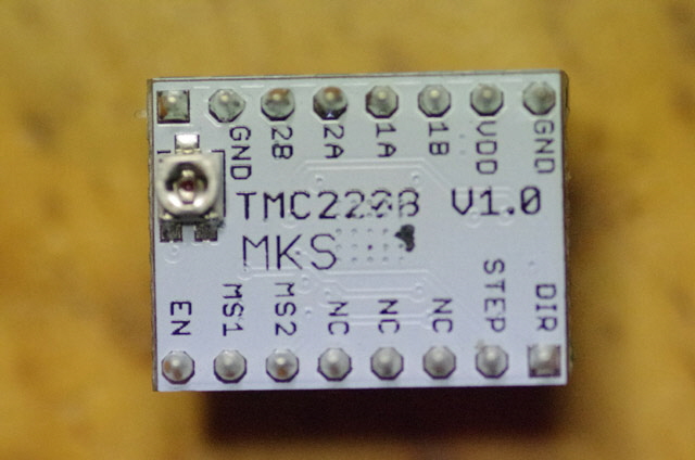
Figure 2. Trinamic Motion Control TMC2208 Stepper Motor Shield
(Top View: TMC2208 V1.0 MKS )

Figure 3. Trinamic Motion Control TMC2208 Stepper Motor Shield
(Bottom View: M-D-X-J-01008)
Installation of the new shields was straight forward. Note the orientation of the old shields from the header pin labels. Remove the old shields by lifting gently upwards from the edges. You’ll need to remove the MS1 and MS2 jumpers and replace one of these in the MS3 position otherwise the stepper motors will half step. Plug the new shields in place and fit the heat sinks on the new shields.
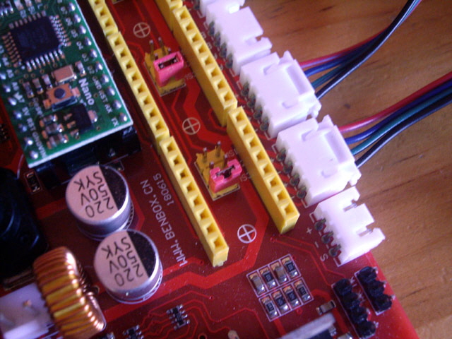
Figure 4. Microstep Jumpers Adjusted to MS3
(Note the 220 uF 50 V Filter Capacitor - should be 330 uF.)
You’ll need to adjust the current set potentiometers on the stepper motor shields. Use the jog controls on your driver software (grblControl) for a large (say 100 mm in X and 60 mm in Y) movement and gently tweak the associated potentiometer to find the ‘sweet spot’ where the motors run silently without skipping.
Now for that direction problem. There are several options for correcting this including adjusting the Aduino Nano firmware, but the easiest solution (by far) is to simply reverse the polarity of one of the windings on each of the stepper motors. I swapped the B+ and B- wires at the stepper motor plug. These are coloured green and black respectively. Power down. Remove a stepper motor plug. Using a pin tool gently lift the connector retaining lug and slide the connector out by pulling gently on the cable. Swap the cables over, reinsert the wires until the connections click home, insert the plug in the stepper motor socket, and the job is done.

Figure 4. Change the Stepper Motor Wiring to Change the Direction
The new stepper motor drivers make for dead silent stepper motor running, a much improved positive lock when an axis is stopped (for example when drilling) and synthesised 256 micro-stepping. There are a whole raft of other improvements available but these aren’t immediately available without accessing the TMC2208 integrated circuit registers. Turn up the volume on this YouTube video link...
CNC Mill with Trinamic Steppers
I tested the new shields with a laser exposure .nc file. Exposure with an 0.2 mm diameter laser spot took just 143 very quiet seconds. But in the silent step StealthMode2 the Trinamic shields are skipping steps under maximum acceleration. This isn’t really surprising as the X and Y stages are relatively heavy compared to what you might expect to find in a 3D printer. After reading the TMC2208 data sheet the solutions appear to be either increasing the motor voltage, changing out the motors, revert to a non-stealth mode, or reduce the acceleration.
I can increase the stepper motor drive voltage from 24 to 36 Volts quite easily. But first I need to determine what the safe upper voltage is for the CNC controller board and stepper motor shields. The XL4015 switching regulator on the CNC controller board is rated for 40 Volts absolute maximum and it won’t need adjustment of the feedback resistive divider to maintain the 12 V supply for the laser. Everything else on the CNC controller board (and particularly the drive MOSFETs) are appropriately rated for the voltage increase. So 36 Volts should be okay.
I don’t have a 36 Volt 5 Amp power supply on hand so I purchased some new 36 V 5A Switch Mode Power Supply modules from China for just $10 each! You can read about putting these in a case, testing and performance by clicking here.
With the stepper motor power supply voltage increased to 36 V the Trinamic drivers work without skipping, but they simply don’t produce enough torque for reliable milling (I can stall them with moderate hand pressure). I don’t want to reduce the acceleration or change out the motors so I’m going to change the TMC2208 mode from StealthMode2 to SpreadCycle. To do this I need to either reprogram the registers on power up, or burn some of the One Time Programmable (OTP) fuses. I can’t readily set the registers because the necessary TMC2208 pin for communication isn’t broken-out on my stepper motor shields. So I’m left with the OTP fuses.
The good news is that I have a fall-back position if everything turns to custard as the OEM A4988 shields provide excellent torque and no skipping with the increased supply voltage. Sure, the stepper motors aren’t silent but, with the spindle motor running, this isn’t really an issue. The stepper motors are running cold and, while the A4988 shields get warm, I can keep my finger on them.
Today I set about reprogramming the Trinamic TMC2208 shields from StealthMode2 to SpreadCycle. There is an excellent tutorial on this at https://www.youtube.com/watch?v=FEgirEyEUbo&feature=youtu.be complete with the software links for ScriptCommunicator and the TMC2208.scez Configurator (a ScriptCommunicator Executable Zip).
My shields have a different layout to those in the YouTube link (they are an early version), I’m using a Pololu USB AVR programmer with TTL break-out (because I have some), and I need to solder a very fine wire directly to pin 14 of the TMC2208 IC, but otherwise the procedure is essentially the same. We’re going to be setting just two fuses: Byte 2 Bit 7, and Byte 1 Bit 1.
When connecting the Pololu USB board make sure you note the TTL COM port - not the STK500 AVR COM port. Ignore the flashing red LED on the board which is indicating that the AVR simulator isn’t powered or talking. Given that my jumper wires aren’t twisted pairs and have a number of joints I have reduced the default baud rate to 9,600 bps which is as slow as the TMC2208 UART will go..
I used double sided tape to secure the Pololu USB board and the TMC2208 shields prior to programming because the wire soldered to pin 14 (PDN/UART) of the TMC2208 is somewhat delicate (just 0.1 mm diameter including heat sensitive enamel insulation). Soldering and removing this wire without damaging the shields was a bit tricky, but successful on all three shields using a very fine tipped temperature-controlled earthed soldering pencil, and some care.
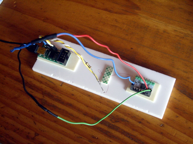
Figure 5. Programmer Hardware Taped to Perspex Sheet

Figure 6. Wire Soldered Directly to Pin 14 of the TMC2208 Integrated Circuit
(This PDN/UART pin has no external break-out connection on these shields.)
The programming was remarkably straight forward following the YouTube tutorial. Note that the updated TMC2208 mode will not be visible in the Configurator settings until the shield has been power-cycled (disconnect, remove, replace and reconnect the USB port to do this).
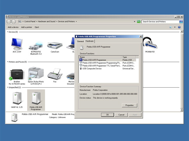
Figure 7. Choose the Correct TTL Serial Port for the Pololu USB AVR Programmer

Figure 8. Initial TMC2208 Status
(Note: EN_SPREADCYCLE is not checked.)
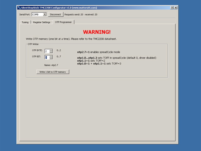
Figure 9. OTP Programming Dialogue
With the first shield successfully reprogrammed to SpreadCycle I tested it in the CNC mill with the 36 V supply. It is working perfectly with no skipping at maximum acceleration, loads of low speed torque and, while not absolutely silent, much quieter than the OEM A4988 stepper motor shields. I didn’t need to readjust the current potentiometer on the shield. I changed the power supply back to the 24 V unit and the reprogrammed shield is still working flawlessly. The final two shields were reprogrammed and fitted along with the original 24 Volt power supply.

Figure 10. Reprogrammed Trinamic Stepper Motor Shields Installed and Running Perfectly
Job done. Link back to the CNC Mill page or use your browser Click to Go Back arrow.
|