|
The following text describes my efforts to build a toroidal winder which ended in abysmal failure due to the quality of a rather expensive Gorman shuttle and spider (the two critical parts that I could not machine). But I’m not done with winding coils and have another project (maglev) that requires a bunch of precision compact and tidy cylindrical coils. If you’re interested in my trials and tribulations with a toroidal winder then read on, but if you’re interested in a cylindrical coil winder click here.
I have need of a coil winder for winding small torodial coils for a tuned pulse transformer used in the Amigo and Amigo Crew. I can wind these by hand using a shuttle, but each coil secondary takes about 30 minutes to wind and just one inadvertent wire twist or too much tension and the applied turns need to be cut away and the winding started again – wasting time and wire.
I have contemplated having these made on contact but the cost is significant and the Minimum Order Quantities (MOQ) are a challenge for limited batch production. New commercial coil winders are a significant investment so I have decided to make my own. This project will also require me to to experiment with stepper motor drives which I have been meaning to do for some time.
Development started with the trying to make a 100 mm diameter winding shuttle and spider to fit what are very small toroidal cores as this was deemed to be the most critical part.. This really tested my machining capability. After four attempts I was getting close to a useable design but I could not achieve an adequate shuttle ring split and I was not happy with the friction in my novel attempts at a spider design. Part of the problem was my choice of material. I started with cast iron because it is self-lubricating but it is far too brittle and I could not achieve an adequate surface finish. However I did make a shuttle that worked reasonably well until I accidentally dropped it and it shattered.
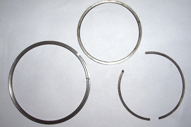
Figure 1. Shuttle Attempts
So next I tried a free machining grade of steel which held a nice finish but reducing the friction between the spider and the shuttle was a challenge. After some deliberation I decided to purchase a commercial shuttle and spider from Gorman.
Gorman seemed some-what sceptical of my ability to make a winder head and reluctant to sell be the parts that I needed. I got quite grumpy because all I wanted was to purchase the part – my risk and no comeback on Gorman. Gorman kindly offered me a second hand winder at a substantial discount but even the cost of this was prohibitive. After much frustration (at both ends of the communication) Gorman finally sold me a shuttle and spider. Thank you.
I have promised not to reverse engineer Gorman’s shuttle, so I can’t provide details of their product beyond what they advertise. But I can advise that my own shuttle concept was very close to their design, with the exception of materials and my inability to figure out how to machine the precision shuttle split (necessary for mounting and removing the core). My spider design was quite different but had comparable shuttle friction to the Gorman product.
Okay, I have a commercial shuttle and spider appropriate for my toroid dimensions and wire diameter. So all I need to make is some bobbins to support and rotate the shuttle and support and rotate the core. How hard can that be?
I started with a concept drawing to make sure that the proposed winder had adequate clearances. Drives are to be provided by independent stepper motors for the shuttle and the core using belt drives.
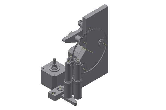
Figure 2. Concept Drawing
I have some 6 mm diameter precision ground shafts with matching phosphor bronze bearings that were rescued from some old laser printer toner cartridges. These should make excellent stub axles for the moving/rotating parts - but if necessary I will fit roller bearings.
I set about making the frame out of some 10 mm sheet plastic and a set of shuttle bobbins out of Acetyl. The bobbin sectional profile was going to be critical in order to ensure adequate drive to the shuttle.
The first bobbins failed. With two driven and one idler bobbin there was insufficient friction between the bobbins and the shuttle to ensure reliable rotation. I figure that the maximum tension applied to the shuttle and spider by the tension arm should be just below the force necessary to cause the shuttle joint to split. When the shuttle is loaded with copper wire this force can be increased significantly but I don’t want the shuttle flying off the bobbins during the last few turns of the winding.
My first thought was to incorporate a small rubber O Ring to increase the friction between the bobbins and the shuttle. This improved the drive but did not overcome the problem. While I had increased the friction between the bobbins and the shuttle I had also decreased the contact area. I had gained more friction than than I had lost but I hadn’t gained enough.
A quick check on coefficients of friction between stainless steel, plastic, brass, aluminium and rubber revealed that my best option was to machine the bobbins from rubber – but machining rubber is a difficult task – so I settled on aluminium as second best.
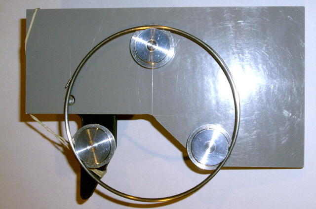
Figure 3. Aluminium Bobbins
The aluminium bobbins provide reliable shuttle drive but there is a problem with the spider. When I stop the spider rotating the shuttle drive becomes intermittent. Either I need to decrease the spider to shuttle friction or increase the bobbin to shuttle friction. I have a few options:
1. Add drive to the idler bobbin. While this will probably work it will add significant load to the shuttle tension lever.
2. Add a rubber tire to the bobbins. This will also probably work but I will need to cast the tires to the shuttle profile – I suspect that this will be too much effort.
3. Increase the bobbin to shuttle force with a compression roller. I am confident that this will work, but the dimensions are small and tolerances are tight to avoid interference with the spider.
4. Increase the surface roughness of the bobbins by etching and hard anodising them. At the moment the bobbins have a highly polished surface finish that feels like glass. This will certainly help and can be applied in conjunction with the other options.
5. Increase the bobbin diameter to provide a larger contact area.
6. Let the bobbins and spider run in for a bit. The machined shuttle profile in the bobbins is not perfect but it will wear in over time. The aluminium is much softer than stainless steel so the bobbins will wear to the shuttle profile. Interestingly the spider to shuttle friction is not completely smooth through a full spider rotation. This will require motor drive which is some way off.
7. Reduce the spider to shuttle friction by expanding the spider ring. I’m not sure what the optimum setting is for this part, but I don’t want it so loose that it comes off the shuttle during winding. In any case this frictional component must be reduced to ensure spider slippage before my 0.1 mm diameter wire breaks.
The least-effort option is etching and anodizing the bobbins so I’ll try this first. Only one mistake – I forgot to mask the stub axle on the idler bobbin. No damage done (other than the end of the axles turning black and corroding slightly) so not to worry. The shuttle drive is now absolutely solid, and with the spider locked it is improved almost to the point of being usable.
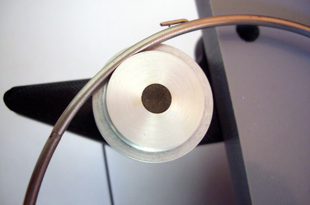
Figure 4. Etched and Anodized
(note the stub axle corrosion)
It is interesting to consider the shuttle rotational angles where the spider is actually retained but wire tension causing the wire to feed, and recognize that the spider doesn't come to a dead stop but progressively slides through the 72° feed angle. In actual use I can expect improved performance because the shuttle to spider friction is dynamic with abut 3:1 slippage.
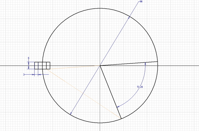
Figure 5. Spider Feed Angles
The drive is not sufficiently reliable for correct spider action. I next experimented with option 5, increasing the bobbin diameter. Although I did not anodize the 38 mm bobbin I did etch it. The increase in drive friction was apparent but not significant.
I am running out of options. With some Bearing Blue I investigated the contact points between the bobbins and the shuttle. There is scope for some improvement here (in effect Option 6). My lathe tool for machining the bobbin grooves was hand-ground but it is not perfect. If use a 2.5 mm diameter drill shaft and improvise a vertical tool holder I will get a much better profile. As a short term expedient I have hand-lapped the existing bobbins with a 2.5 mm drill shaft and metal polish. This destroyed the anodizing which will need to be re-done.
Time also for some more research. The designs that I could find with a similar bobbin configuration all seem to drive the idler roller (Option 1) often with a double belt. Their bobbins are about the same diameter as mine, some in brass, some in aluminium and some in plastic. None have a compression roller (Option 3).
My next step is to design and make the tensioning blocks because holding everything aligned by hand and using rubber band tension straps is a bit hit and miss. The blocks are a simple 3D printed design with an embedded nut. I’ll be using 20 mm long compression springs from a cheap ball point pen. I’ve made two compression blocks because I may need one for a compression roller, should this prove necessary. The tension block is fitted with only one retaining screw because I messed up with my marking out, inadvertently drilling a previous centre-mark. I guess I’ll be making a new frame in due course in any case.
With the tension block fitted I decided to try the idler roller drive (Option 1). Now we’re in business! The shuttle and locked spider drive are good to go. I figure that I will be re-making the bobbins, perhaps with a slight increase in diameter, and etching and anodizing them again. I will also be providing a wide flat belt drive.
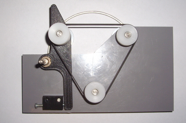
Figure 6. Tension Block Fitted with Flat Belt Idler Bobbin Drive
My next mission is to make some more drive pulleys (the ones shown in Figure 6 are my failed attempts at using Acetyl for the shuttle drive), fit the existing frame to a base and get the shuttle motor drive up and running.
The wide flat belt concept failed due to poor pulley design (at least the driving pulley needs to be crowned to prevent belt wander) so I will be making some more pulleys today for a double square belt drive. I am getting good at making these now and can can turn one out in about 15 minutes, but I have turned a lot of plastic into useless round wheels refining the machining process!
Here is the final shuttle drive prototype ready for motor testing, complete with the frame mounted to a base plate. The dual belt action is both smooth and positive. There are two sets of belts to keep the motor drive and shuttle tension independent. I have allowed sufficient space between the motor pulley and the frame to allow for ready belt replacement. However the base could be smaller without affecting stability by cutting the motor shaft to length. I also want to re-work the tension block in due-course because I have an idea for improving on the current arrangement.
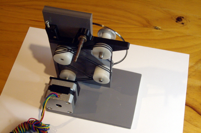
Figure 7. Motor and Belt Drive
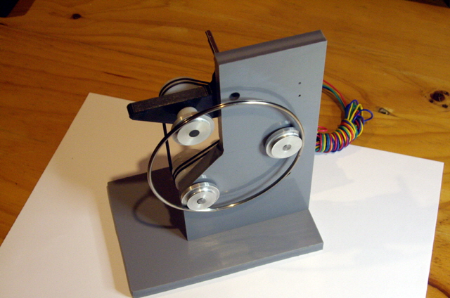
Figure 8. Shuttle Side
I’m hoping that my next post on this page will be a UTube link to the motorised drive test. If this is successful then the design is about half done. The next stage will be the toroid drive and I am concurrently working on the software and drive electronics.
Shuttle Drive Being Driven
Well the shuttle drive is up and running. As you might expect here have been a few issues along the way. However the basic drive is reliable and the shuttle, bobbins and pulleys are nicely aligned with minimal friction.
Movie 1. Click on Image for YouTube Link
The first was that the motor pulley and the idler bobbin spacer were not dead square with the square with their respective shafts. I remade these parts, adding a boss to the motor drive pulley and taking a little more care when fitting it. Note that all of the rotating parts are a press fit - there are no grub screws at all in the design. I also took time to remount the tension block so that it is securely held by two machine screws.
I can’t find the maximum stepping rate for the motor. The fastest I step rate I can drive it with no load is about 5 kHz with 1/8th micro-stepping before it locks up, even with a gradually increasing step frequency during start-up. The fastest step rate under load is about 4.6 kHz . The shuttle is turning at 32 RPM with/or without spider lock. The motor drive current is about 115 mA without spider lock and about 120 mA with the spider locked.
The motor speed should be exactly 4597 Hz / (360° / 1.8° / 1/8) * 60 = 172 RPM. The pulleys are all approximately 23 mm in diameter, the bobbins have a drive diameter of about 17 mm and the shuttle is about 94 mm in diameter. So the shuttle speed should be about 42 RPM. Replacing the shuttle with a belt the actual shuttle drive speed was measured at about 40 RPM. I am still loosing too much speed due to bobbin to shuttle slippage.
My suspicion that this is due to a lousy bobbin drive groove profile was confirmed with a small wipe of Bearing Blue on the shuttle and a few rotations under motor drive. There is also some contact between the side of the shuttle and the flange on the bobbin. The flange was incorporated in the design to assist in fitting the shuttle and prevent it from getting jammed between the bobbins in the frame in case it came loose. However the flange should not be making contact with the shuttle under normal conditions because I deliberately machined 2° of taper to ensure clearance. I need to remake the bobbins using a precision 2.5 mm diameter tool (discussed above), decrease the flange diameter and increase the clearance angle to say 5°.
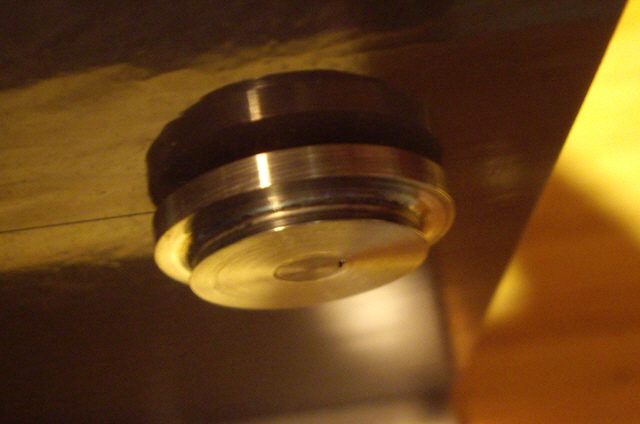
Figure 9. Typical Bobbin Contact Surface
(Really hard to photograph, but Not Good!)
Aside Comment. Common uses of Bearing Blue are to locate high and low spots between mating surfaces and to increase the definition of marking out lines (I should have used some when I first fitted the tension block). I purchased my first and only tube of Bearing Blue more than 30 years ago for hand-scraping a mild steel surface dead flat. In some respects it is like mustard - you will waste more than you actually need at every application. However despite use every month or so, my 25 ml tube is only a third consumed, the contents are as good as the day it was purchased, and I expect there will still be heaps when I am long past on.
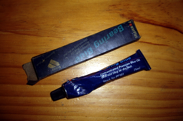
Figure 10. Bearing Blue
The next revelation is that the motor speed is too low for my application. At 32 RPM my windings will be done in about three minutes plus set-up time. I want to get the winding time below a minute including ramp-up and down. I will have to experiment with increasing the motor drive voltage above 12 V, finding a more appropriately specified motor (and/r driver), or changing some pulley ratios.
As an experiment I loaded the shuttle with some 0.25 mm wire and with a toroidal core (both somewhat larger than the intended application) and with the core hand-held, attempted a winding. The spider friction is way too high but the drive powered on through making a really nasty mess of the winding until the wire eventually jammed the shuttle and I had to turn the power off. On close inspection of the spider I found some rough patches on the inner surface. I’ll be attempting to polish these out and expand the spider a bit in the hope of reducing the spider to shuttle friction. I have come to the conclusion that this must be minimal - just a tad more than the minimum required to hold the wire in the shuttle at maximum shuttle speed. I have seen larger winders where the spider would rotate to the bottom of the shuttle under gravity! Of course it may be that the shuttle itself has a poor surface finish in its groove. I will be looking at this too.
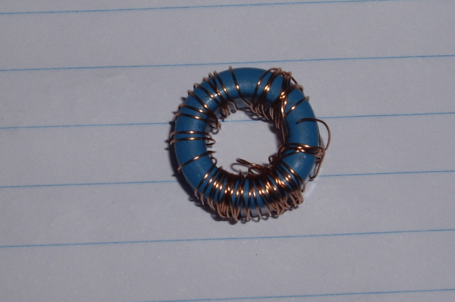
Figure 11. Can I call this my First Winding Under Power? - Nah!
(For scale the core OD is 16 mm)
I have increased the stepper motor drive from 12 to 24 V and can increase the step rate to over 10 kHz. However the torque drops so any increase in shuttle friction at these speeds causes a stall. The driver micro-stepping is not working well at low speeds. There is insufficient torque with partial winding current to force the micro-steps which results in single step skipping. I have two more things that I want to experiment with on the driver board - disabling the micro-stepping and implementing fast current decay.
The stepping oscillator is currently a ubiquitous LM555 running as an astable square wave oscillator with a duty cycle of approximately 50%. For my further tests I have replaced this with an LM331 linear Voltage to Frequency converter with a frequency range from 0 to about 12 kHz. While the circuit is somewhat more complicated than the 555 it allows me to manually ramp up the drive frequency with a potentiometer.
After running at 10 kHz for a about an hour nothing was getting warm (other than the 5 V regulator on the driver card - a design issue in my mind) but a high pitched squeal suddenly developed in the drive. The problem was friction between the inner face of the bobbins and bearing. A tiny drop of oil on the bearings stopped the squeak. It also resolved the drive slippage. At 10 kHz we have 68 RPM on the shuttle - and there is no longer any measurable slippage which must have been occurring on the belts.
I have finished my experiments with the stepper motor drive and have concluded that I will need a motor with an improved torque/speed characteristic curve for the shuttle drive. However my existing motors should still be useful for the core drive and maybe some other applications.
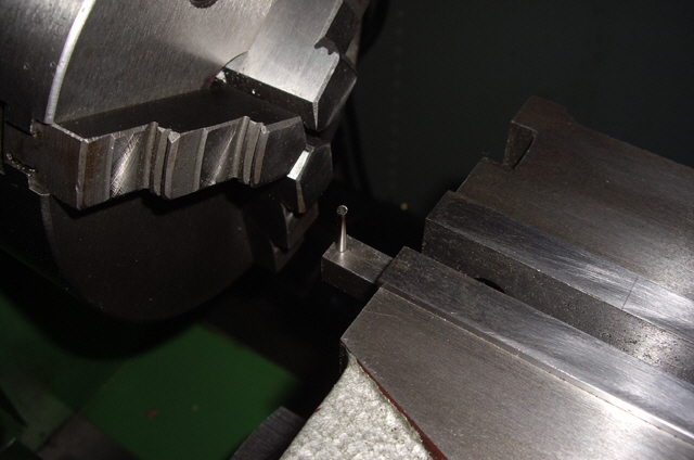
Figure 12. New Bobbin Profile Tool
I made a new profiling tool for the shuttle drive bobbins today. It is simply a 2.5 mm diameter HSS drill shaft case hardened. Rather than make the new bobbins I re-profiled the old ones, and also increased the side clearance angle to the flange from 5 to 10°. After reassembly I checked the fit using Bearing Blue and the results are far better than I had achieved previously. The Bearing Blue has formed a blue sheen over the the entire shuttle seat showing a wide and even contact surface. This will be even better once the bobbins are etched and anodized.
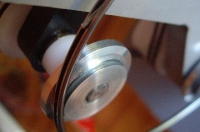
Figure 13. Bobbin Shuttle Contact
(Compare with Figure 9. This is now acceptable.)
Re-profiling has reduced the drive diameter of the bobbins and they need to be re-etched and anodized so they will still need to be remade at some point. This has also caused the tensioner to reach the end of adjustment. However the shuttle drive has been operating at about 35 RPM for several hours without a hitch and I figure this will be adequate for testing the core drive.
There is still an issue with the spider-to-shuttle friction which remains too high. The shuttle is now dead smooth after careful polishing but the spider is still rough. Years back when I learned to shear the process of finely honing the cutters and combs on a shearing hand piece was called ‘experting’ and it improved the cutting performance of the shears significantly. As the shuttle drive is working reliably I am now experimenting to see if this friction problem is a running-in issue or a more insidious problem with the surface finish of the spider and/or shuttle
The Gorman shuttle and wire spider is proving to be a significant problem for my design. With the spider gently formed to 94 mm diameter there is still significant friction between the spider and the shuttle and it actually increases over run-time. Further, the wire has a tendency to back-feed and jam between the spider the the shuttle wall. This shouldn't be possible.
I have checked my drive and it provides less than +/- 0.04 mm eccentricity at the bobbins and next to no measurable lateral play. The shuttle shows +/- 0.1 mm eccentricity at the core position although this measurement is influenced by the Dial Indicator Gauge (DIG), causing a slight flick when the shuttle split joint passes. I cannot readily measure the shuttles lateral movement at the core position because it deflects readily under the DIG, but it is +/ 0.03 mm at the bobbins. So the bobbins and the shuttle drive are fine.
Next I set about measuring the shuttle and the spider. I took at least 12 measurements of each important dimension around the circumference using vernier calipers to within 0.01 mm. The measurement summary is as follows.
Spider width: 0.90 to 0.91 mm.
Spider depth: 0.79 to 9.00 mm (not good).
Shuttle width: 2.47 to 2.49 mm.
Shuttle depth: 2.04 to 2.11 mm.
Shuttle OD: 97.89 to 98.00 mm.
Shuttle Groove width: 1.12 to 1.19 mm (not great).
I can conclude from these measurements that the shuttle and spider combination that Gorman sold me is not suitable for copper wire under 0.3 mm diameter. Once the wire jams between the spider and the shuttle the winding is toast.
My next check was the ‘blind test’ taught to me by an engineering instructor a long time back. First, look at the surface for any obvious imperfections. Then close your eyes and run your finger nail tip across the part. You’ll be amazed at what you can feel even if you can’t see it.
Now for a review with a USB microscope. The spider has a number of significant surface defects including lateral tooling marks, pitting, wear and what appears to be tearing and peeling of chrome plating. The shuttle it in relatively good order with nice smooth surfaces including the inside groove and only minor defects at the split joint and groove edges (the latter probably caused by the spider).
Here are the USB images. Note that here is some dust on the CCD that I haven't been able to clean yet (these show up as black specks) and camera’s the depth of field is somewhat limited at this magnification.
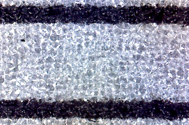
Figure 14. USB Microscope Scale.
( Approximately 1 mm between line centres.)
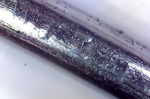
Figure 15. Chipping and/or Machine Marks on Face of Spider!
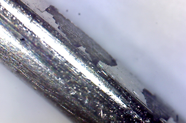
Figure 16. Failed Plating on Spider
(The plating is probably chrome.)
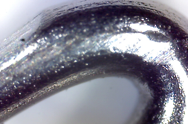
Figure 17. Significant Wear on Spider Pickup
(Upper left is contact wear with the shuttle which is right through the chrome plating.
Middle right is copper wire feed area. There is no way that my limited tests have
caused this damage.)
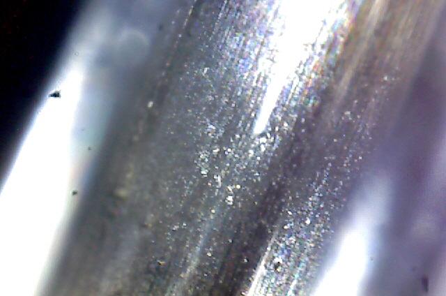
Figure 18. Base of Shuttle Groove
(Clean and smooth.)
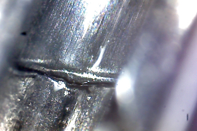
Figure 19. Shuttle Split Joint at Base of Shuttle Groove
(Not perfect but smooth.)
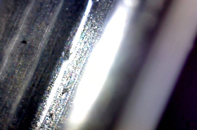
Figure 20. Minor Pitting of Shuttle Groove Wall
(probably caused by the state of the spider.)
There is no way that my limited testing with the spider has resulted in this much wear. The parts have been handled with care and I have only had three attempts at winding just 5 shuttle turns of copper wire from the shuttle. My test jig has only been operating for a few hours at about 64 RPM and with very low torque. The Gorman spider would be useless in any coil winder and the parts clearly don't meet my wire specifications. A cynic might think that Gorman had sold me parts that would ensure that my design would fail so they could say ‘we told you so’, and were laughing all the way to the bank.
Okay, I need a new shuttle and spider as I have already determined that I cannot reasonably machine these parts. I’ll try another company and see if they can provide a better product. If I can find a positive locking hinged shuttle gate and a conventional side slider then this design will come together. Otherwise I’ll be converting the design to some form of belt shuttle drive. The new parts will probably necessitate a new drive bobbin profile so everything is on hold for now.
After some research and further experimentation (including 3D printing a number of alternative spider designs for the Gorman shuttle) I have come to the conclusion that, for my small cores, I need to change the design approach to a belt winder. This will have a number of positive outcomes including improved shuttle drive, the re-use of the Gorman shuttle with just a small amount of rework to remove the pitting on the groove wall, and increased internal core clearance. I need some more 10 mm plastic sheet for the new frame and I’ll be changing to roller bearings and a timing belt for reduced friction and more positive drive.
While I’d like to continue experimenting with this project my need for a coil winder is becoming pressing. Looks like I’ll be finding a commercial unit (no change from $5,000).
|