|
While the essence of this page is making a ball bearing tilt switch, it is also about another 3D print project and repair of an electronic travel alarm clock.
I have a travel alarm clock which was a gift about 20 years ago. The clock isn’t a Rollex but it does has a novel feature of changing mode from a second timer to temperature, then world time and then regular time by changing which side sits on the bench. I use the temperature and timer functions in the server room for monitoring the ambient temperature and as a handy stop-watch for estimating program computation time.
The date function is stuffed (software limited to 2010) and the world time rotary switch has always been a bit flaky but otherwise the clock has been useful until recently when the case orientation function swapping become unreliable. There is no point in having a stop watch that you can’t start reliably, and getting the clock back to ambient temperature mode is a trial.
I pulled the clock to bits. A quick Ohm meter check showed that the ball bearing switches are intermittent. My first thought was to simply throw the clock away, but maybe I can repair it by refurbishing or remaking the switches?
There are two hexagonal switch blocks aligned at 90°, each with two switches. I removed the cover off the first one and there is a gold plated ball bearing that shorts between two pairs of wires depending on the switch vertical orientation. The ball bearing looked in great order. The gold plated wires have some wear but the plating seems to be intact so I figure that then less than secure mounting may the cause of the problem?
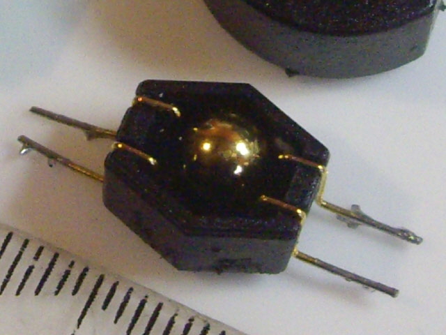
Figure 1. Original Tilt Switch (case removed)
In attempting to remove the cover from the second switch block two of the tracks lifted off the PCB. Bugger! This repair job has just become a little bit more difficult. With the switch block case finally removed the contact wires also appear to have no significant wear and the ball bearing is in good order.
I figure I can make replacement switch blocks using the existing ball bearings, some gold plated component pins and 3D printed cases.
Way back mercury was used for tilt switches. It is relatively dense, has a high surface tension and readily wets electrodes but it isn’t particularly environmentally friendly, is highly toxic, and needs containment because it has a low vapour pressure. I won’t be using mercury tilt switches for this application.
I spent a couple of hours redesigning the case to ensure that the ball bearing would always short the pins when vertical and would make no contact when horizontal. I have calculated that assured contact will occur within 20 degrees of vertical for my design. Unfortunately I can’t readily calculate the contact angle for the old switches because of the cradle electrode form but I figure it is around 20 degrees.
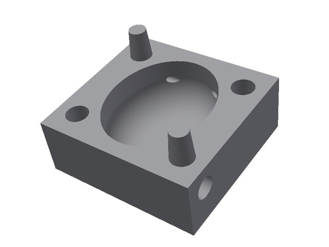
Figure 2. New Tilt Switch Symmetrical Half Case Model
A refinement is reducing the ball bearing contact with the pins from 4 to 2. In essence this doubles the contact force to half the weight of the ball bearing. The bearing is still free to roll horizontally supported on the pins which should assist in keeping the contacts clean.
The new contact pins are mounted at both ends and are therefore more secure than the originals.
The ball bearing cavity was changed from extruded hexagonal to oval (egg shaped) with a significant reduction in size. The final case dimensions were 10.8 mm long x 10.2 mm wide x 8.2 mm high compared with the original at 15.2 mm long x 13.2 mm wide x 8.6 mm high.
With leads, the original switch block length was 25 mm. I figure that part of the problem with the origin design may have been using the contact wires for mounting. So I’m going to securely mount my pins in the case and use flying leads to the PCB. The terminals add a total of 2 mm to the width of my design which is still smaller than the original. I’m going to mount the switch blocks to the PCB with adhesive or double sided tape as there are too many PCB tracks for through holes.
It is apparent from the 1 second switching action delay that the contacts are discharging a capacitor through a resistor. This is a typical low cost switch debounce arrangement and avoids inadvertent clock mode changes due to vibration or movement.
The model case was 3D printed in two halves with mating spigots to ensure alignment and, after testing, are glued together. In retrospect I should have used 2 mm machine screws for joining the case halves which would have allowed for disassembly. The pin and spigot holes were over-drilled to ensure a tight press fit.
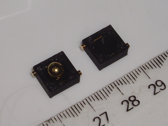
Figure 3. New Tilt Switch Ready for Assembly
The print itself was very straight forward taking about 5 minutes for both halves of the case after bed heating using a medium resolution. The internal cavity walls are nice and smooth and the spigots (which are only 1.5 mm in diameter and tapered) are well formed and adequate for purpose.
The ball bearing and the pins were cleaned using IPA and lint free tissue, assembled in the case without hand contact, tested, case glued together, retested, adhered to the PCB and connected. I soldered the flying leads directly to the pin terminals in the assembled case without incident but this clearly risks distorting the case. On the next switch block I plan to solder the leads to the pins before these are inserted in the case.
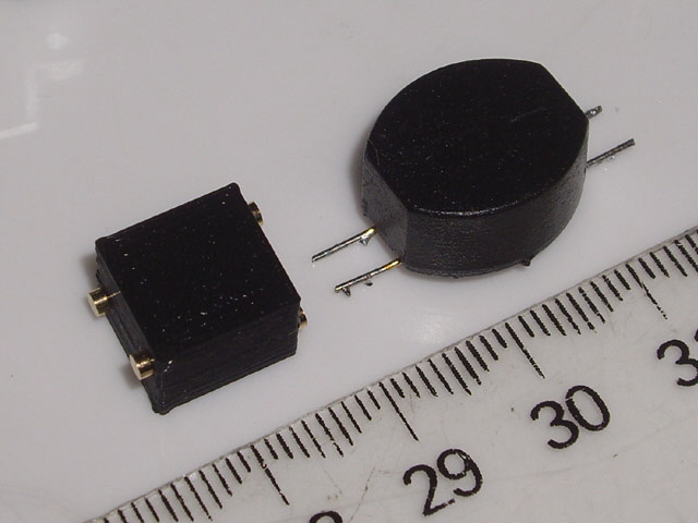
Figure 4. New and Old Switches
The second switch block had an issue with reliable contact after gluing. On disassembly there was an errant ultra-fine plastic or glue thread, and some plastic film on one of the pins. Unfortunately the case disassembly was destructive so with some difficulty I extracted the pins, cleaned them, and reprinted the case. Note that I’d love to use cyanoacrylate adhesive (Super Glue) on this job but this is highly mobile and I don’t want to coat or contaminate the ball bearing or pins. I used my all time favourite Acrifix 192 Perspex adhesive.
With the switches adhered on the PCB and connected I set about repairing the three damaged PCB tracks with soldered flying leads. As an aside I use a Verowire pen for this sort of patch wiring. The wire has self-fluxing insulation which makes for tidy track repairs, jumpers, and flying leads. My wiring pen is over 30 years old and still serviceable. You can still buy these for about $40 from Vero Technologies
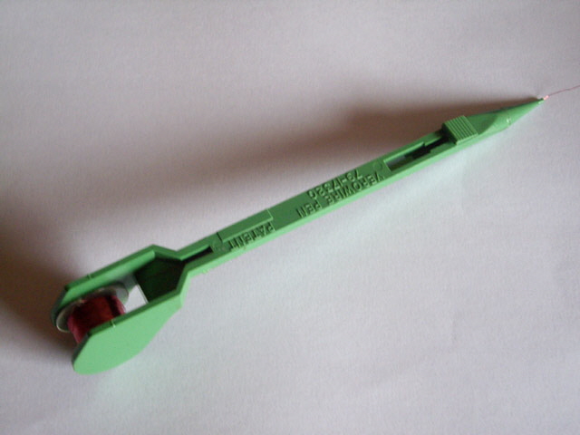
Figure 5. Verowire Pen
While I’m messing with the clock I decided to have a look at that flaky rotary switch. Two problems are apparent. The external dial and the internal rotor arm have insufficient clearance for the case width which causes the switch to jam. Secondly there is enough slop in the switch to allow the perimeter of the rotor to catch on another part of the plastic housing. A simple spacer washer and trimming the housing has fixed the rotary switch which now turns relatively freely between indents.
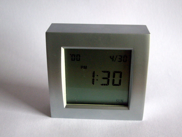
Figure 5.
The clock is now serviceable and the tilt switches work beautifully. However the date won’t be correct for another 90 years. The clock is back in the server room monitoring the ambient temperature and as a stop watch for monitoring program runtime. Job done.
|