|
I need some thermally conductive adhesive for my still.
The still has been repaired quite a few times over the last 15 years. The original design failed when the studs that secure the aluminium heating element to the stainless steel pot failed at their spot welds. This increased the thermal resistance between the element and the pot causing the thermal cut-out to trip before the water in the pot was boiling.
My very first repair involved re-welding the studs to the stainless steel pot using my CD welder quite some time back I applied some white electronic thermal grease to ensure good thermal contact between the pot and the element because air is a very poor conductor of heat and the still’s thermal trip operates at 120°C. The element must be tightly thermally coupled to the pot otherwise the trip actuates before the water in the pot starts boiling, and close thermal coupling is necessary for maintaining reasonable thermal efficiency.
In more recent times I have repaired the electrical sockets and plugs with substantial and secure 3D printed plastic housings as the old ones had become brittle and loose over time. I also silver soldered a new connector on the thermal switch which broke during maintenance through repeated cable flexing.
Over the past few weeks the still has been in almost constant use replenishing our emergency water supply following a 7.8 Richter Magnitude earthquake a few weeks back. The quake shook up sediment in the water supply pipes resulting in brown water with an unpleasant taste and a perceivably gritty sensation in the mouth. While the water was apparently potable (the sludge was always in the pipes and in contact with the water) the local authority recommended that the water should be boiled. We went straight to our emergency supply for a week.
With our emergency water supply almost restored and the tap water clear the still stopped working. The thermal trip was triggering just as the water was starting to boil.
I disassembled the still and found that a couple of the stud welds had failed due to corrosion and the thermal grease had entirely tried out leaving a dry gritty yellow/white powder with no surface wetting capability and intermittent surface contact.
The longevity of thermal grease is an issue. It comprises an oil or grease base loaded with an insulating conductive powder (usually zinc or tin oxide, but sometimes aluminium nitride). Over time and at elevated temperatures the base evaporates leaving the filler, with no wetting action on the applied surfaces, air-filled voids and generally poor thermal performance. If you ever had cause to replace the heat sink on a CPU or graphics card you will know exactly what I am talking about.
First up I needed to reattach the failed studs. After a few experiments I used silver brazing which provided a more robust joint than the previous stud welds, although this did cause minor heat distortion and discolouration of the stainless steel pot. The brazing required some tidying up with a Dremel to ensure reasonable contact between the pot and the element. On reassembly (without thermal grease) the thermal trip still kept actuating early. So the thermal contact between the element and the pot was inadequate.
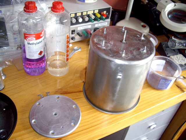
Figure 1. Studs Re-attached and Element Cleaned
I applied some thermal grease and the trip problem was resolved. It worked only when the pot ran dry. But this was simply setting myself up for another repair job in the future when the grease eventually dries out. Perhaps I could prevent this by replacing thermal grease with a thermal adhesive that would not dry out over time?
Electrical insulation of the thermal adhesive in this application isn’t an issue. In fact it is desirable to improve earthing of the pot and element housing.
We can calculate an estimate of the desired thermal transfer coefficient of our adhesive between the element and the water in the pot. The trip sensor activates at 120°C and is good thermal contact with the element. The element has a name-plate rating of 565 W. When the pot has water in it its temperature will remain at about 100°C. The diameter of the aluminium heating element is approximately 175 mm (slightly smaller than the diameter of the pot base with an area of 0.0241 sq m). If we ignore the temperature gradients through the aluminium element casting, the stainless steel pot, assume that all of the element heat is transferred to the pot, and assume an even adhesive thickness of 1 mm, then the thermal conductivity of the adhesive needs to be better than:
Even with close-fitting and relatively flat metal surfaces we will struggle to achieve the desired transfer coefficient without thermal paste or adhesive because physical metal to metal contact is limited to the high points on both surfaces. The element finish is quite rough and the pot base is not dead flat. If we assume an air barrier exists between the element and the pot then the air thickness to achieve 1.17 W/mK must be less than:
Heat transfer will be improved by any material with a heat transfer coefficient better than air that will fill the voids between mating high spots.
For my thermal adhesive I plan on using a two part epoxy resin loaded with as much thermally conductive power as possible, limited only by the viscosity of the adhesive.
Epoxy is thermally stable at temperatures up to about 180°C which will be fine for this application but it has a relatively low thermal conductivity. References suggest epoxy has a thermal conductivity of about 0.35 W/mK but fibreglass is around 0.04 W/mK which is only twice that of air!
Selection of the filler is important. Here is a list of thermal conductivities of some materials at 300°K – some of which aren’t candidates due to cost, availability, or toxicity.
Filler Conductivity (W/mK)
Diamond >1000
Silver 429
Beryllium Oxide 424
Copper 401
Graphite 293
Aluminium Oxide 30
Zinc Oxide 25
Air 0.025
The best material I can reasonably source is copper but I need fine copper powder. While I could file down some copper the resulting grains are relatively course even using a smooth or dead smooth file and it will take an age and lots of physical effort to produce enough for my needs (estimated to be about 20 ml).
Copper powder can be made by placing iron, zinc or another metal higher in the potential series in a solution of copper sulphate. This works quite well and copper sulphate is readily available at most garden stores. However I still need powdered iron or zinc which means more filing, and I’ll need enough of these materials and copper sulphate (the source of the copper) to produce sufficient filler.
However we can also make copper dendrites using a simple electrochemical cell with an inert anode, a copper cathode and an acidified copper sulphate electrolyte. The resulting dendrites are small spongy cones with a large surface area that, if necessary, are readily refined by simple mechanical grinding.
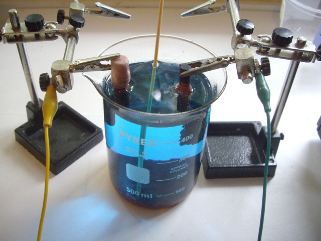
Figure 2. Electrochemical Cell
After some reading and experiments I settled on a carbon anode from an old zinc carbon D cell (battery). I tried lead, chrome plated steel and stainless steel anodes but these ended up with an adhering copper plating as opposed to forming easily removed copper dendrites.
I also experimented with a number of surfactants in the electrolyte to improve the dendrite formation and reduce adhesion to the anode. These included soap, detergent, sugar and glycerol. Glycerol worked best.
Here is my recipe.
Electrolyte: Copper sulphate: 5 g/l
Sulphuric acid: 50 ml/l
Glycerol: 10 ml/l
Distilled Water to make up 1 litre
Anode: Carbon rod (D Cell)
Cathode: Copper rod
Current Density: 1.7 mA/mm2 of anode area
Cell Voltage: 2.5 V
All of the required materials should be readily available from garden shops, automotive outlets and your local pharmacy. Alternatively they can be made (synthesised) with just a little effort.
I mixed up 500 ml of the electrolyte in a beaker. When mixing the electrolyte remember to always add acid to water and never the other way around or the acid may boil and splatter. Copper sulphate is poisonous and sulphuric acid is both toxic and corrosive. Take appropriate precautions when handling these materials (goggles and rubber gloves are a good start).
During cell use gas will bubble from the electrodes and may cause minor splatter of the acidic electrolyte so make sure that the experiment is conducted on a suitable surface that will not be damaged. The splatter may also corrode the electrode connections over time so be sure that these are expendable.
The DC current source was a 12 V 20 A bench power supply. The cell voltage was adjusted to 2.5 V by using series resistors (effective resistance of 4.7 Ohms, 20 W) with a current of about 2 A.
In operation the copper dendrites form on the anode with steady hydrogen emission due to electrolysis of water. Oxygen is evolved at the copper cathode as it steadily erodes. The electrolyte gets warm over time. If the current density is increased then the copper deposition rate also increases, but at the risk of boiling the electrolyte.
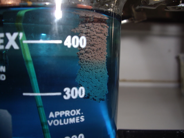
Figure 3. Copper Dendrites forming on Anode
The dendrites simply wipe (or eventually fall) off the carbon anode and settle at the bottom of the cell. Make sure that there is enough clearance between the electrodes and the bottom of the cell to prevent a short circuit forming as the copper dendrites accumulate.
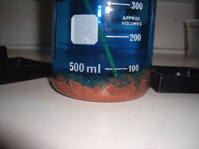
Figure 4. Dendrites Accumulating at the Bottom of the Cell
Unlike the zinc/iron in copper sulphate solution approach this method will keep producing copper dendrites as long as the current is on, the copper cathode is intact (it gradually erodes over time) and the electrolyte volume is maintained by adding distilled water to compensate for evaporation and electrolysis.
If you are interested in the chemistry then there are plenty of on-line references and that you can refer to (try Googling Electrolysis Carbon Copper) and many chemistry texts (try Inorganic and Organic Practical Chemistry by F.C. Fulker, Whitcomb and Tombs, 1963 as a useful primer).
I kept the cell running over three consecutive days during waking hours to produce about 100 ml of copper dendrites (uncompressed as settled at the bottom of the cell). The bulk of the electrolyte was decanted off (and saved for another day).
The 90 g copper cathode was almost entirely consumed producing about 84 g of dendrites and a 6 g copper stub.
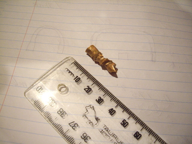
Figure 5. Cathode Stub
The copper dendrites were thoroughly washed with distilled water and air dried. Keep the drying temperature low (well below 100°C) because the copper dendrites have a huge surface area that will readily oxidise to black copper oxide. Even with air drying the pure copper will darken from salmon pink to dark brown. If you want to retain the pink colour then I suggest drying in a vacuum desiccator.
The copper particle size is typically less than 0.02 mm with most significantly less than this. The largest particle I could find in my sample had a dimension of about 0.05 mm. There were a few larger pieces of copper plate from my anode experiments. I removed these manually but they were very flat and could easily have been incorporated in the adhesive without undue effect. The dried copper powder doesn’t feel gritty when rubbed between ones fingers.
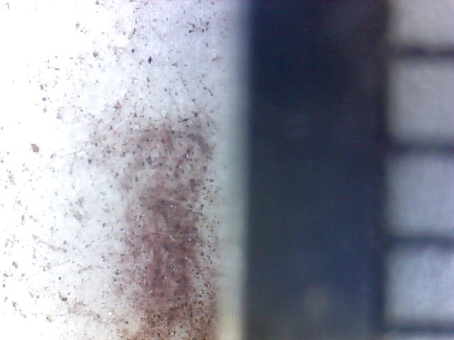
Figure 6. Copper Dendrites (Right Hand Graduations are 1 mm)
The adhesive was mixed by adding the prepared copper powder to 10 ml of epoxy resin until it reached the consistency of treacle (golden syrup) followed by 2 ml of hardener (5:1 epoxy mix ratio). The resulting adhesive contained about 68 g of copper to 14 g of epoxy (about 80% w/w loading).
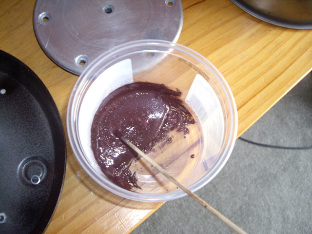
Figure 7. Mixed Epoxy and Copper Adhesive
The thermal adhesive was spread onto the pot base and the element to ensure wetting. The parts were then mated, pulled apart to check for even coverage, remated, and bolted together using the mounting studs. Excess epoxy oozed from the edges of the joint as the stud nuts were tightened and was wiped off.
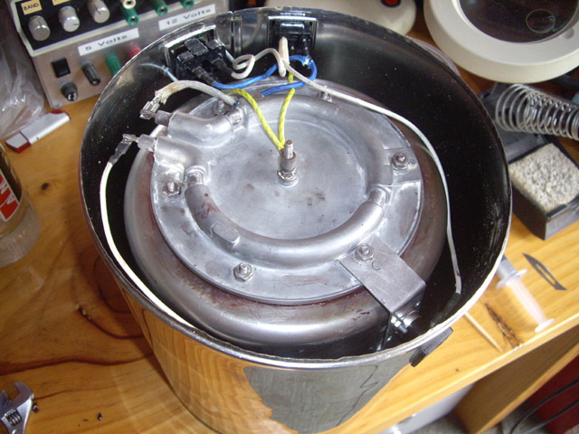
Figure 8. Element Adhered to Pot and Bolted in Position
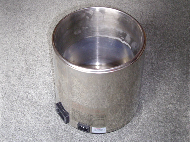
Figure 9. Still Boiler Reassembled
I made a little too much adhesive for the still repair. I took some of the excess and applied it between two pieces of 25 mm square x 1.25 mm thick aluminium sheet for some comparative thermal performance tests later on. The dried thermal adhesive layer was about 0.4 mm thick. The physical bond is excellent. I can’t separate the plates by hand.
Epoxy cured with heat has better mechanical properties and an increased upper temperature limit so I reassembled the still, filled the pot with water and turned it on to aid with the epoxy chemical curing process. The still worked first time and the thermal trip only activated once the pot had boiled dry (just as it should) .
The adhesive flows under gravity before curing but eventually sets hard chocolate brown with a glossy smooth exterior finish.
Electrical conductivity of the set adhesive was measured at about 1 Ohm with needle probes approximately 1 mm apart pressed into the surface, however the measurement was not consistent depending on the location and pressure applied to the probes. However the electrical resistance between the two test aluminium rectangles was a dead short. Electrical conductivity requires particle-to-particle contact in the epoxy matrix which bodes well for good thermal conductivity. If electrons can flow freely through metal contact then so can heat.
The still is working just fine with the thermal adhesive but we only have a rough estimate of its thermal conductivity at better than 1.17 W/mK based on our initial calculation and a number of assumptions.
In order to get a better idea of actual thermal conductivity I attached the 25 mm square aluminium test piece to a 5 W resistor dissipating 3.68 W using silver base thermal paste and pressure and measured the maximum resistor temperature over 20 minutes. The resistor was embedded in fibreglass insulation with natural convective cooling through the test piece at the top.
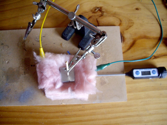
Figure 10. Comparative Measurement of Thermal Conductivity
With an ambient temperature of 18°C the measured maximum temperature of the resistor was 127.0°C with the copper adhesive.
I repeated the experiment with silver based thermal paste between two similarly sized aluminium plates. The paste thickness was set to 0.4 mm by two small paper spacers. The maximum resistor temperature was 132.7°C.
Finally, as a reality check, I repeated the experiment without any thermal compound between aluminium plates. The maximum resistor temperature was 161.0°C after 20 minutes and still rising slowly.
I repeated the experiment on all three samples three times. The copper always performed better than the silver (the minimum temperature differential of 5.7°C between copper and silver is reported above) and both performed better than air.
The first ‘result’ from the experiment was that thermal paste is really messy and gets on everything while thermal adhesive is clean once set.
The copper adhesive appears to perform somewhat better than the silver thermal paste with a stated thermal conductivity of 3 W/mK. The experiment was crude because it relies on a relatively constant ambient temperature of 18°C and it is difficult to ensure that the insulation conditions and placement of the temperature probe and each sample are identical. However the results were not unexpected as silver and copper have similar thermal conductivities and the copper loading in the adhesive was significantly greater than the silver loading in the commercial paste (80%:25%).
Note: While this job needed a good long term thermal adhesive I won’t be using this as a heat sink interface on semiconductors any time soon. The filler particle size and size range in the commercial silver paste is much less than in my copper adhesive and the surfaces in these applications are flat and smooth. This allows for comparatively very thin thermal paste layers with better heat transfer performance than this adhesive. Further, adhesive may make semiconductor upgrades or replacements difficult.
So the still is repaired and I have a recipe for an effective thermal adhesive. Job done!
Well not quite. The still has been action again for several weeks and this afternoon it failed again with the original symptom - thermal tripping while the pot contained water. Bugger! I pull the still to bits again to investigate. The aluminium heating plate was still securely adhered to the pot and getting them apart required a chisel and some well-directed brute force. The two studs failed during separation - the adhesive was stronger than the original stud weld!
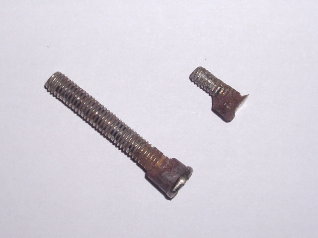
Figure 11. Failed Studs with Epoxy Still Attached
The epoxy had failed and started to char right at the point where the thermal sensor was connected to the element. Char occurs at around 200°C so it is not surprising that the thermal sensor was tripping. What could have gone wrong this time?
The bulk of the epoxy was still the original chocolate brown colour and was well adhered to the element and pot. When cracked the epoxy showed bright pink copper.
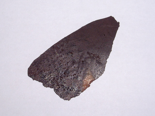
Figure 12. Overheated Expoy/Copper
(Note the bright pink copper at the chip.)
I figure that the issue is in part the different rates of thermal expansion between the aluminium element, the epoxy, and the stainless steel pot. Heating to 120°C results in a differential movement of almost 1 mm between the epoxy and both metal components across the full width of the heating element. The epoxy bond has broken on the pot surface beneath the thermal sensor mount. The resulting poor thermal contact probably caused local heating further degrading the epoxy. This would have lead to a progressive run-away to failure.
The epoxy/copper thickness and it was 0.85 mm in places - more than twice the anticipated thickness. I suspect that I need to improve the mechanical fastening of the element to the pot.
IThe originally manufactured stud welds were never satisfactory (these were the original cause of still failure) and through progressive repairs the pot base has become distorted. If I replace the studs with stainless steel through-bolts with washers then I can achieve a much better fit between the element and the pot. Some form of thermal gasket material is still desirable. Maybe copper powder in silicone rubber will perform better than copper powder in epoxy? Silicone rubber has a higher operating temperature than epoxy, should be flexible enough to permit differential expansion, and should form an effective water tight seal between the bolt heads and the pot. The thermal conductivity of silicone rubber is somewhat less than epoxy but this should be offset by the reduced clearance achieved using through bolts. Washers will be used to retain the silicone around the bolt head for an effective water tight seal and to distribute the compression between the pot and the element.
I removed all traces of the original adhesive and the studs from the pot and the element by chipping and grinding followed by polishing with a wire brush. Then I carefully drilled seven 6 mm diameter holes through the pot base using the element as a template.
I made another 75 g of copper powder for this experiment.
There are a few potential issues with silicone rubber in a gasket application. The first is the relatively short working time which is perhaps just 10 minutes. The second is achieving cure over a relatively large gasket area, and the third is the relatively high viscosity which may make for an unduly thick and porous gasket.
I set up an experiment with a range of solvents (straight silicone, glycerol, methylated spirits, MEK, turpentine, and mineral spirits) with Selley’s neutral cure marine RTV silicone. I mixed a few drops of solvent with a small dab of silicone and applied this at 0.63 mm thick between two microscope slides. Then I added approximately an equal volume of copper powder to the remaining mixture and mounted this between the slides as well.
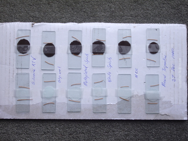
Figure 13. Silicone RTV Thinners Test
The glycerol mix turned opaque white suggesting that the mixture was actually an emulsion. The remaining mixtures all retained the clarity of the base silicone RTV. Mineral turpentine and methylated spirits provided the best thinning action. However the viscosity and work time for the un-thinned silicone RTV was not going to be a problem provided that it cured in a reasonable time.
RTV (Room Temperature Vulcanising)neutral cure silicone cures through the action of atmospheric moisture (humidity). A wide thin gasket or a heavy section will take a long time to cure as the outer layer skins and vulcanises, preventing moisture from permeating to the inner silicone. However if you have ever left the cap of a tube of silicone you will know that it will cure throughout the tube (or canister) over time.
I’ll leave the test slides for 24 hours and inspect them for cure, adhesion and porosity.
Straight silicon RTV only cured about 5 mm in from the edges, but the copper mix cured across the full diameter of the sample. Mineral turpentine worked well but with the same cure issue without copper. Glycerol was hopeless, making a white sticky uncured plastic goo. The copper aided curing and the resulting film had good flexibility but poor surface adhesion. Methylated spirits performed similarly to Gylcerol but with bubbles in the copper mix. White spirits and MEK had also developed bubbles in the copper mix with a distinct odour of RTV and solvent. However the copper mix was rubbery and had adhered well.
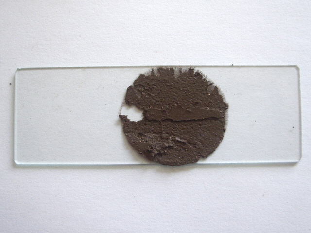
Figure 14. Silicone RTV/Copper Worked Best Without Solvent
The copper powder seems to aid curing either as a consequence of residual moisture content, by catalytic reaction. I doubt that this is due to the formation of voids allowing moisture to permeate through the adhesive.
With the experiment completed I settled on a 50:50 v/v mix of silicone RTV and copper without solvent. Assembling the element was pretty messy as I was trying to work quickly as the silicone RTV copper mix started to cure within minutes of being mixed. The underside of the bolt heads and the interior of the pot were coated in straight silicone RTV before tightening to ensure that the pot remained water tight. There was some ooze from the edges of the element as the bolts were progressively tightened so I figure that there should be good contact between the element and the pot base, but maybe I could have used slightly less copper powder?
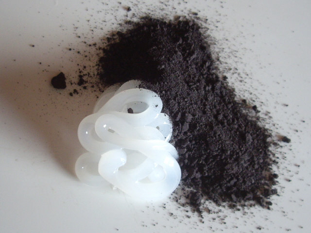
Figure 15. Silicone RTV and Copper
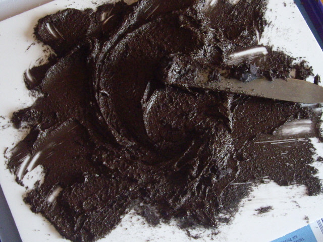
Figure 16. Mixed Silicone RTV and Copper Adhesive
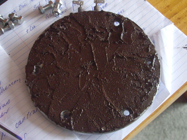
Figure 17. Adhesive Applied to Element
I reassembled the still, torquing down the new stainless steel through-bolts and left it for a couple of days to allow the silicone RTV to cure. Time to test the still. It heated up to boiling and then the thermal trip actuated again. This is becoming annoying. With the element still warm I disassembled the still and removed the element. The silicone RTV/copper layer had formed a thin even mat with no bubbles. The adhesive was still quite soft and sticky but did not appear to have wet the surface of the aluminium element very well. The adhesive readily peeled off the pot base in a continuous thin sheet (in effect a thermal mat).
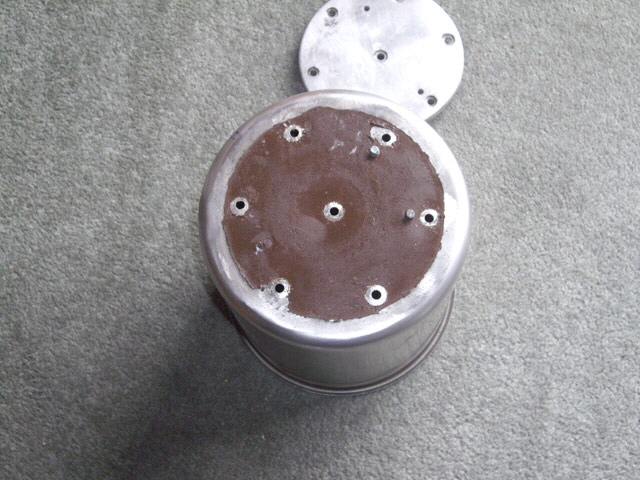
Figure 18. Partially Cured Silicone RTV/Copper Adhesive Mat
(following disassembly after thermal trip failure)
Something else is happening here. I would have expected that with the 6 mm stainless steel through bolts the still should work even without thermal paste because there is a secure distributed mechanical and thermal connection between the element and the pot base. On further inspection I think I have found the cause of the problem. The thermal trip is mounted on an aluminium right-angle bracket that is securely attached to the element by one of the 6 mm bolts, but the other end is held rather loosely against the pot wall by a stainless steel clip (see Figures 1 and 8 above). In an earlier repair I had replaced the two M3 machine screws that fix the thermal trip to the bracket, but the new machine screws did not have countersunk heads. The thermal trip was in excellent thermal contact with the bracket, and the bracket was in excellent thermal contact with the element, but the bracket had a very poor thermal contact with the pot. So the thermal trip temperature is pretty much driven by the element and not between the temperature of the element and the pot.
I replaced the thermal trip machine screws with countersunk heads and tightened the clip on the side of the pot to hold the bracket securely to the side of the pot. The bracket was now in good contact with the pot.
We have had another severe earthquake today and I want to be making some more distilled water. Rather than mix up an entirely new batch of thermal adhesive I applied commercial silver based thermal grease between the element and the pot base, and between the bracket and the side of the pot. With everything re-assembled the still was back to normal operation.
While the still is now working I figure that the silver thermal paste will dry out over time resulting in eventual failure. For now I’ll be making another 40 litres of distilled water before replacing the silver paste with silicone RTV and copper powder, perhaps with somewhat less copper to improve the element wetting action.
More to follow...
|