|
The spindle motor on the XK7113D is rated at 2.2 kW with a top speed of 12,000 RPM. It has ceramic bearings and requires water cooling. The spindle motor MUST only be operated with water cooling. On first use the spindle motor should be run-in progressively over about an hour starting at a relatively low speeds without load. Failure to run the spindle motor in may reduce its service life.

Figure 1. OEM Hoses for Spindle Motor Cooling
The mill comes with a 230 VAC 75 W submersible pump with a rated output pressure of 3 m of water and a flow rate of 3,000 litres an hour for spindle motor cooling. The pump is hard wired to the controller cabinet.

Figure 2. Submersible Pump for Spindle Motor Cooling
Use distilled water for the spindle motor cooling in the first instance, although there may be benefit to adding corrosion inhibitors or antifreeze in cold climates. The cooling circuit is best configured as a closed loop from a large (say 10 litre capacity) container with a lid to prevent ingress of swarf and other contaminants. It can also be configured as open loop to drain from a suitable water supply, but note that domestic water supplies may not have adequate water pressure to achieve the required flow rate for effective cooling, and this arrangement is not environmentally sustainable as waste water goes straight down the drain.
Running In
I need to run the spindle motor in at progressively increasing speeds with water cooling for a period of about 30 minutes. The spindle motor was toggled on very briefly at 1,000 rpm without the pump. This seems to be working and turning in the correct clockwise direction. Next I toggled the pump dry very briefly (flood in Mach3) to check it was working. All good so far.
Next I connected the pump up to the spindle motor tubes and set it in a 20 litre bucket of water with the intake screen fully open. I started the pump using Mach3 but it wouldn’t run or pump, and everything else stopped (including the axial jogs and the spindle motor). There was a chattering noise in the control box, caused by the relays that drive the contactors rapidly switching. Something isn’t right.
I reset the machine and control computer (power off reset) but the problem persisted.
The only thing I have done is submerse the submersible pump and this cannot be the cause. There is no easy way of disconnecting the pump for a test so I disconnected it from the contactor in the control cabinet. The lead resistance is about 90 Ohms which I figure is about right. I wired it to a test lead and placed it back in the bucket with a short length return hose. The pump is working just fine directly off the mains. Finally I tested the electrical leakage to the water. Nothing untoward here.
With the pump disconnected I reset the mill and control computer and everything has come back to life. I hate intermittent errors like this because you can never be sure what has caused the problem. It looks like either Mach3 or the controller board have had a software error.
I rewired the pump to the contactor. On restart the pump is running and pumping just fine. I reconnected the hoses to the spindle motor (note these don’t seem to have a any particular inflow or outflow polarity) and turned the pump back on again. The pump is working but nothing is coming out of the drain tube? There must be a blockage in the pipe or spindle motor.
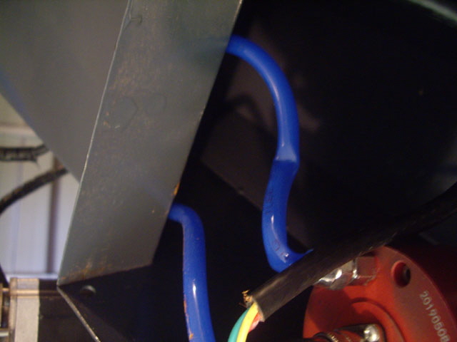
I need to remove the cowling covering the spindle motor and see what is amiss. On removal (eight hex machine screws) the intake tube has been crushed and bent closed right above the intake nipple on top of the spindle motor. This explains the lack of water flow – just like a pinched garden hose. This must have been done during assembly and can’t have ever been tested at the WMT factory. I cannot straighten the crimped tube out. It needs to be replaced.

Figure 3. Cooling Tube Crushed and Bent
(Note the poor wiring termination at the spindle motor plug.)
I removed the hoses and the spindle motor plug (which is polarized for correct insertion). The spindle motor plug assembly has also been poorly assembled by WMT. The cable clamp screws are loose and, in any case, the cable sheath has been stripped too far back so the clamp clamps to nothing. I’m going to replace the cooling tubes with something longer (say 5 m) and rework the spindle motor plug.
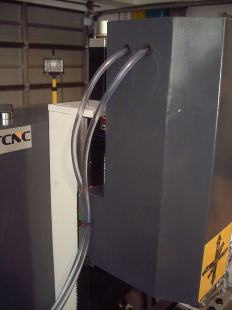
While I’m about it I’ll be moving the tube ports from the top of the cowling to the left hand side, adding grommets to protect the tubes, and adding a tube tie-off to keep the tubes from flopping about and well away from the bed.
With the work done the spindle motor is now effectively wired and water cooled.

Figure 4. Cooling Tubes Replaced and Moved to Left Hand Side of Cowling
(Note the inclusion of rubber grommets to protect the tubes.)
With the cooling on I ramped the motor speed up 2,000 RPM every 5 minutes or so to 12,000 RPM. Nothing is getting hot or sounds out of balance. The cooling water remained cool to the touch. So we’re ready at last to try some tool path traverses before actually attempting to cut some metal.
I’ve trimmed the new spindle motor cooling tubes to length, fitted some rubber feet (supplied by WMT) to the base of pump, and fitted a lid on the cooling water tank. The lid is actually quite important to keep swarf and dust out of the water. It also reduces the possibility of pumping water over the shop floor.
After a few weeks of working on other aspects of the XK7113D CNC mill the spindle motor cooling water has gone slightly rusty and there are several very small steel or iron filings in the bottom of the tank. I suspect that these may have got into the tank during some of my modifications. I’ve cleaned out the tank, flushed the pump and motor, changed out the water, and re-tested the pump. I’ll be adding some automotive corrosion inhibiting antifreeze to the tank. This imparts a nice green colour to the cooling water which will help with determining that the cooling lines are full.

Figure 5. Rust in Spindle Motor Cooling Tank
Spindle Motor Variable Frequency Drive
After some correspondence with WMT I finally have the users’ manual for the BEST Variable Frequency Drive (VFD) , Model: FC300-2.2G-S2-B4C. I have also received a slightly different manual directly from BEST.
First up I painstakingly went through and manually recorded all 160 parameters (P000 to P159). This is melt-down and user-induced-fault protection. If it all turns to custard then I should be able to reset everything. A CNC mill without a spindle is like a pub without beer.

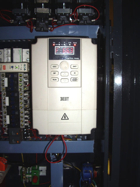
Figure 6. Variable Frequency Drive
Note that a lot of the VFD parameters are actually at the factory defaults, but not all of the settings seem appropriate. Many of the factory reserved setting show ‘-’ in the display but some show parameters that can be changed? I’m guessing that this a documentation issue with the controller manual.
With a users’ manual I can now navigate the VFD display. The only immediate problem that I noticed was that the RPM display is twice the actual Mach3 programmed motor speed? The VFD parameter P057 has been changed from the factory default of 30.00 to 60.00. But the spindle motor is rated at 12,000 RPM at 400 Hz so it must be a four pole motor:
WMT have incorrectly programmed the frequency to RPM parameter for a two pole motor. I have reprogrammed this parameter correctly.
The VFD frequency display is now almost correct, but slightly below the set value by about 22 RPM at set speeds of 1,000 and 2,000 RPM. At this stage I’m not sure what the actual motor speed is so I can’t be sure where the problem lies. However the actual spindle motor speed seems to be about right based on a finger placed on the chuck at 1,000 RPM. The motor is spinning in the correct direction (clockwise when viewed from above) with plenty of torque, the speed appears to be nice and steady, and the motor accelerates and decelerates smoothly. Note that the VFD manual states that the RPM display is the ‘Approximate mechanical speed = output frequency * speed frequency ratio’.
The default VFD display setting can be changed from frequency to RPM with parameter P056. Once I get around to actually measuring the spindle motor speed I’ll consider changing the display to RPM and putting a Perspex window in the controller cover so it is visible without having to open the control cabinet.
The VFD has two relay contact sets available for switching stuff. They appear to be controlled through parameters P101 and P102 (currently set to activate on fault condition). There are no ratings in the manual but the relays are SONGLE SRA-24VDC-CL. They have a 24 V coil driven by the VFD and the contacts are rated for 20A 125 VAC. As a future modification I might configure these to control the spindle motor pump contactor so the spindle cooling pump always comes on with the spindle. The existing flood cooling relay can then be used to drive a cutting fluid pump or sprayer. This modification will wait for now.

Figure 7. VFD Relays
I’ve used a laser tachometer to measure the actual spindle speed. It is running about 25 RPM below the programmed speed. At a programmed speed of 2,000 RPM the measured speed was 1980 +/- 2 RPM. At a programmed speed of 1,000 RPM the measured speed was 976 +/- 2 RPM. So the VFD RPM display is actually correct. This minor variation could be compensated for in the VFD parameters but a 1% variation is speed is not going to be important.
I have also reconfigured the spindle motor cooling pump to operate from the Y2A and B normally open relay contacts through an external relay rated at 240 VAC 10 A. The spindle cooling pump now turns on and off with the spindle motor. This ensures that the spindle motor will always be water cooled, and frees up the M3 gcode command for operating a flood cooling or misting pump for cutting fluid.
Click here to link to Home Switches.
|