|
Before I can power up the machine I need a bench to get the bed at about 900 mm above the concrete floor slab. It needs to be very strong and robust and I want it to be readily movable. I sketched up a design that should meet these requirements and set about making it up from timber.
The basic structure is 4 x 4 legs with 4 x 2 rails joined with glued mortise and tenon joints. The top is 25 mm thick structural ply and three of sides are fitted with 12 mm thick ply shear brace panels to prevent racking. A shelf on the lower rails provides a home for the MACH3 driving computer.
The bench may need to be bolted to the floor to prevent the machine from ‘walking’, but first up I’m going to try level adjusting rubber feet which should also act as dampers to absorb vibration.
I set about making the bench. The timber is untreated pine. Making sixteen tight and clean mortise and tenon joints took the best part of a day. The assembled frame is dead square and the top is level.
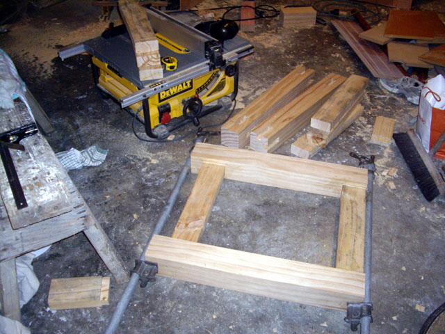
Figure 1. Making the Bench Frame
With the frame assembled I needed some material for the top and the shear braces. My local timber merchant doesn’t stock 25 mm structural ply so I cut up a sheet of 12 mm ply and laminated three pieces to make a 36 mm thick top. I also purchase a second sheet of ply for the sheet braces. It’ll take a day for all that adhesive to go off. When laminating ply make sure that the sheet grain is opposing between layers to maximize the strength of the final product.
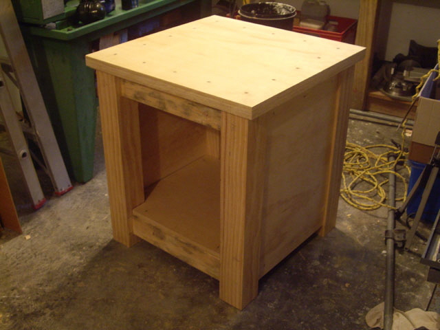
Figure 2. Bench Almost Complete
I also need a large tray under the machine just in case I decide to run cutting fluid. I’m not sure how much excess spray I will get from the tool at 12,000 RPM but if this is a problem then I’ll need a misting nozzle too. I have a plastic tray on order but the sides may be too high and need cutting down.
I’ll need some holes in the sheet braces for the cabling and ventilation for keeping the computer cool. While the computer will sit protected from swarf and the like, I’ll also need a shelf and/or stand for a keyboard and monitor. I figure that if the machine is relatively vibration free then I can mount these off the stand using draw rollers, or make a hinged fold up extension. I’ll hold on this for now.
For mobility I was thinking crank-down or retractable caster rollers. But I found a cheaper solution called ‘Lift and Roll Set’ at just NZ$23. It is only rated for 150 kg but floor is pretty flat and I’m hoping that I won’t be moving the machine too often. I weigh about 75 kg and I can stand on one of the four dollies and it doesn’t fail so the set of four should handle 300 kg.
The mill bench is pretty much done and it’s as solid as brick pagoda. I made up a set of fittings for the
M10-1.5 thread leveling and vibration-damping feet and fitted them into the base of each leg. The feet are a few days away but I figure that, with the fittings installed, I can fit the feet without having to remove the mill from the bench.
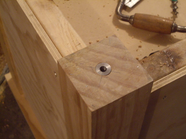
Figure 3. Home Made M10-1.5 Steel Fittings for Leveling Vibration Damping Feet
(rated at 500 kg)
Tomorrow will be the trial fitting of the CNC mill for best positioning, marking out the mounting bolt holes, and bolting down. The only tricky part will be the lift. If the machine were to drop it would definitely break the concrete floor, damage the mill, and crush anything in between. Interestingly there are no apparent lift points on the machine other than the bed mounting holes. I’ll be taking this nice and easy with a mind to protecting me, the machine and the floor.
Ideal mounting has the Center of Gravity (CoG) of the machine above the centre of the bench. Movement of the X and Y axes will move the CoG, so the best we can do is assume a mid-axial positioning. I expect that the CoG will be near the axis of the column, and perhaps slightly forward towards the spindle.
The lift was straight forward using a 1 ton endless chain and appropriately rated tape strops under the base of the machine and around the sides of the bed. The strops were loosely secured to the column to keep everything upright.
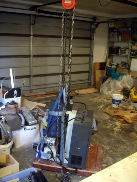
Figure 4. The Big Lift
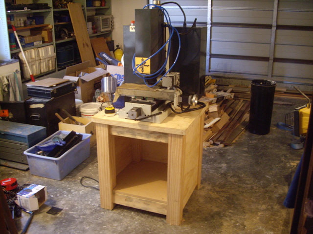
Figure 5. On the Bench
With the machine on the bench I completed a further inspection and opened up the control cabinet. Everything is looking good and wiring looks tidy (but on closer examination it is not so good - link to electrical for details). Note that there is no wiring or schematic diagram for the control cabinet and WMT don’t provide this. However it shouldn’t take too long to work out what the modules are, what they do, and find their individual data sheets.
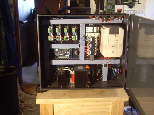
Figure 6. Control Cabinet
Next I manually manipulated the X and Y axes. The action is dead smooth with absolutely no slop or back-lash apparent. The Z axis has a brake on top of the stepper motor so it can’t be manually adjusted. Manipulation will need to wait for configuration of the control computer.
Tray
My new tray folded from 1 mm galvanized sheet steel has arrived. The base of the tray is 750 mm x 550 mm. The brazing on the corners isn’t great but the join is sealed water-tight. I cleaned up the bird-shit brazing with a file and spent a few minutes painting it with zinc enriched gloss epoxy enamel spray paint but it needs to sit for a few hours to dry and harden. I’ll be fitting this, the new leveling, vibration damping feet, bolting the mill to the bench, and completing preliminary leveling tomorrow. This will mean a few holes in the tray sealed with rubber compression pads. I’ll hold off on fitting the tray drain for cutting oil for now.
Note: If I were making the tray again I’d be increasing both the width and length by about 100 mm to facilitate fitting machine guards.
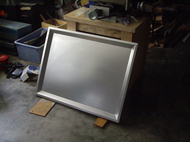
Figure 7. New Tray
We’re almost ready to start actually operating the mill under CNC control. I’ve ordered some additional 3/16” short shank carbide end mills along with a bunch of spiral fluted taps. While I already have a collection of milling cutters some of these are only good for roughing after years of use and occasional abuse. The new machine tools will be here by the time the mill has been tested and spindle motor has been run in. The taps are for use with my regular mill with a self reversing tapping chuck. This will save a whole lot of time on tapping the three threaded holes in the parts that I need to make.
Leveling Vibration Damping Feet
These fitted perfectly first time and work very well. Setting is easy. Position the bench and wind the feet fully home. Check for any rock and wind out the errant foot until stable. Place a spirit level on the mill bed X axis and wind out the two legs on either the left or right hand side of the table until level. Now turn the level 90 degrees to the y axis and wind out the front or rear legs for level. We’re dead level and stable.
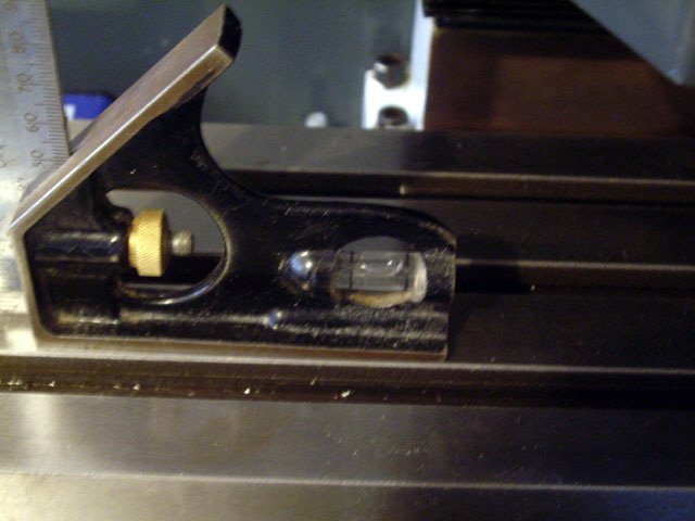
Figure 8. Dead Level and Stable
Mounting
There are no drawings provided with the machine for the mounting bolt hole locations and measuring them isn’t straight forward. Perhaps the easiest way to mount the machine is to simply position it on the surface, mark the hole centres directly from the base holes, and drill an appropriately sized hole for either an anchor or a mounting bolt. This means moving the machine a few times which is tricky given its weight. The holes cannot be drilled using the base bolt holes as a guide because there is insufficient space for a drill and this risks damaging the cast iron base. A better technique is to take the dimensions straight off the holes in the shipping base-board. But here is a dimensioned drawing complete with the bed travel limits.
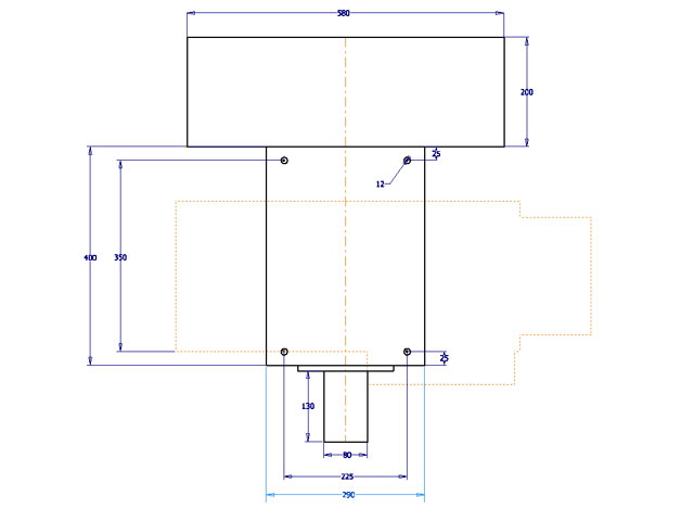
Figure 9. CNC Mill Footprint
In transport the mill was held down with two M8 bolts to the base board. The base plate holes are ~12 mm diameter but they won’t quite take an M12 bolt. M10 is the closest standard metric diameter. I’d like to locate the bolts from the top down but this makes it next to impossible to form a cutting-oil tight seal with the tray. So I’m mounting from the bottom up, with a rubber compression washer secured by a flat washer and nut for the tray seal.
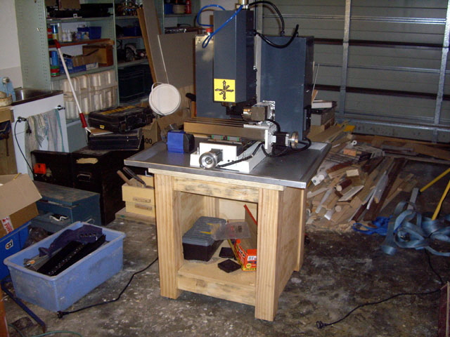
Figure 10. CNC Mill Bolted Down
I’ve knocked up a desk for the control computer monitor and keyboard from scrap timber. In retrospect I should have made it about 200 mm wider, but it is certainly better than a piece of MDF balanced on two cardboard boxes. Although there doesn’t look to be much space for the mouse this hardly ever gets used when machining. Mach3 is designed to be driven by Hotkeys.
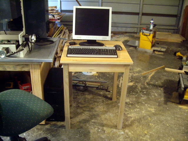
Figure 11. Desk for Monitor and Keyboard
Inspection and Clean Up
Before I proceed too much further it’s time to inspect and clean up the machine. I’ve had it in the shop for almost three weeks now, so I might have attended to this earlier. Protective grease has been applied to some of the machine surfaces but the coverage at the factory wasn’t adequate. The consequence of weeks in a shipping container is prolific bloom rust on unprotected surfaces. The bloom rust is primarily on the bed and at the base of the column but there are spots elsewhere including the black hex key machine screws on the column and the Z axis brake. The grease and bloom rust need to be removed and the surfaces relubricated with machine oil. There is also some swarf in the tee slots. While this isn’t an immediate problem (swarf will collect here in use) a brand new machine should not have any swarf from manufacturing at all. I have started removing the grease and cleaning back all of the bloom rust with a wire brush, 1,200 grit abrasive, followed by a wipe down and copious application of oil.
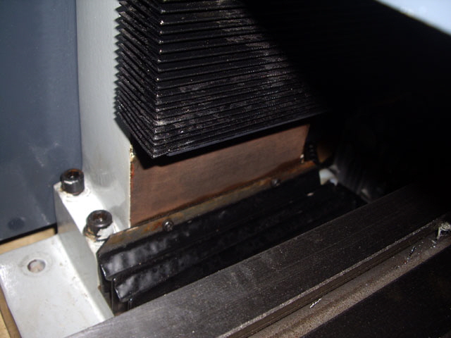
Figure 12. Bloom Rust at Base of Column
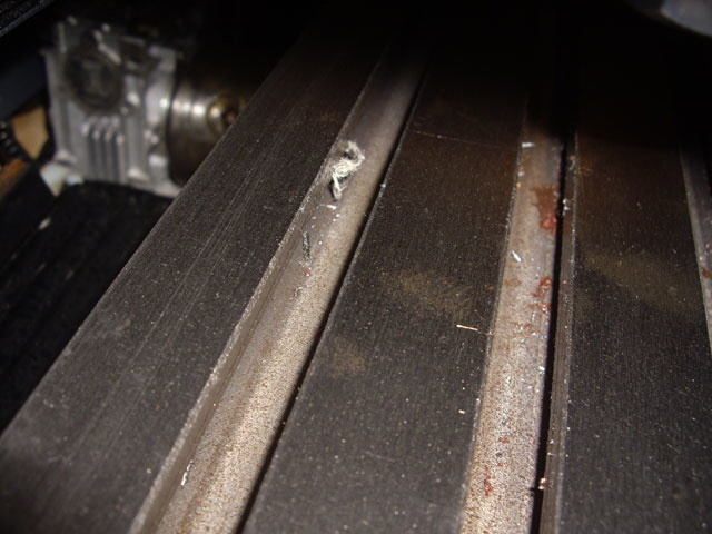
Figure 13. Swarf and Rust in the Tee Slots
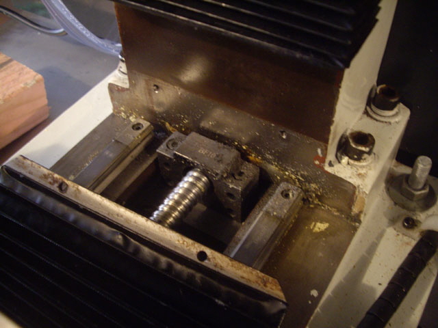
Figure 14. Swarf and Debris Under Y Axis Rear Boot
With most machines it is good practice to clean the machine down and lubricate machine and bearing surfaces, lead screws and the like after a period of time or number of operating hours. Mach3 records the operating hours and axial travel distance. There are grease nipples on each of the linear bearings (more on packing these will follow below) but lubrication extends to the ball screws, rails, and all bearing surfaces. The manual provides minimal guidance. My usual practice is to clean down machine surfaces between jobs as necessary, and clean and lubricate all machine surfaces at the end of each day.
Click here to link to the Manual.
|