|
I’ve recently had cause to turn 1.5 kg of brass scrap into useful solid round stock so I could do some machining. The casting process produced enough solid metal for the job at hand, but it was pretty rough and ready sand mould with two cylindrical patterns with no relief angles and open at the top of the cope. The pouring basin (which was too small) was placed between the mould cavities connected by two gates.
The small pouring basin resulted in metal overflow, charring the wooden flask and causing me to skip the pour (halt it temporarily) which is not good casting practise.
The furnace worked very well with the crucible initial charge molten in just 15 minutes and another 15 minutes to complete the charge to 1.5 kg total weight.
There was a lot of white fluffy dross on the melt which I assume was oxidised zinc and there was a distinct silver-gray skin on the castings which was condensed zinc. Apparently this can be avoided (or at least minimised) by tilting the flask so that the base of the sprue remains choked.
So far my rigging (sprue, runner, gates and risers) design has been somewhat adhoc and my experience is certainly limited. I have some more brass to melt so I have decided to try using a more systematic rigging design approach to see if I can improve the results.
Old-timers that have spent their lives in sand will probably have a laugh at this, simply look at the desired casting and immediately come up with an effective and efficient rigging system. Unfortunately I meet the age criteria but without enough time playing in the sand pit. A documented systematic approach should work, and if it doesn’t then at least I’ll have a reference from which I might improve.
Note that there are numerous publications on rigging design, many of them contradict each other (and occasionally themselves) and many contain errors in the basic physics. I’ll be referring to some of these but otherwise I’ll be trying to use physics to work out the design.
Regrettably, most of this page will be text and equations (but nothing too daunting) as there isn’t too much I can take pictures of.
With the next melt I’ll be adding some zinc to replace the oxidised material and degassing with a small amount of aluminium. You can obtain some really clean zinc from a few discarded zinc carbon batteries. Simply hack saw one cut down the case. The battery should peel apart nicely leaving a clean zinc case, a carbon electrode, some paper and plastic, a steel shell, and a heap of gooey black powdered graphite and manganese oxide in a paste of zinc and ammonium chloride. While we are only interested in the zinc all of the other stuff is recoverable and can be separated if you need it.
Don’t try and get zinc from alkaline, lithium or lead acid batteries. While these are a ready source of other useful stuff they don’t contain zinc.
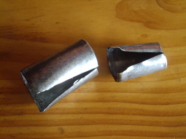
Figure 1. Zinc Battery Cases
Ideally the casting height should be as small as possible but I can’t be bothered making a split cylindrical pattern. I’ll be sticking with two vertical right cylinders 40 mm diameter and 70 mm high made of Perspex. Even though these have no draft they release from the sand cleanly with just a bit of rapping (tapping the pattern before withdrawing it from the sand).
I’m going to be 3D printing the rigging system because this ensures good sand compaction with relief angles and fillets, and will cost just a couple of dollars in plastic. If it works it will also be re-usable for similar future casting projects.
The rigging design process starts with the volume of the casting and its surface area. My cylindrical patterns have a volume, V, of:
pi d2 / 4 * h = 3.141 * 402 / 4 * 70 = 87,964 mm3
The surface area, A, is:
pi d2 / 2 + Pi d * h = 3.141 * (402 / 2 + 40 * 70) = 11,309 mm2
The principle volume modulus of each patterns, Mv, is therefore:
Mv = V / A = 87,964 / 11,309 = 7.8 mm
Mv is a measure of the comparative cooling rates of a casting, parts of a casting and the rigging system. A higher value of Mv indicates a comparatively slower cooling rate. For a given volume a sphere will have the lowest cooling rate possible (minimum surface area).
However for relatively long objects Mv reduces to two dimensional heat loss in the section plane, Ms, because there is little cooling down the length of the section a long way from the ends (say more than 5 times the maximum section dimension):
Ms = section area / effective cooling perimeter
This implies that a long cylinder will actually have a lower cooling rate away from the ends than that of a sphere with the same diameter (by a factor of 2/3 if you do the maths).
The weight of each our castings, W, is:
87,964 mm3 * 0.0085 g/mm3 ~ 750 g
0.0085 g/mm3 is a reasonable estimate for the density of solid brass. Note that the density of molten brass is somewhat lower than this. It can be estimated from the anticipated 4.5% volume contraction on solidification as:
0.0085 g/mm3 * (1 – 0.045) = 0.0081 g/mm3
I also need the total weight of cast metal including the rigging which hasn’t been designed yet. I’ll estimate the rigging volume as 50% of the castings and check this later - if I am totally out of the ball park then I’ll need to do redo the my rigging design (in essence an iterative design process).
So the total weight (which is state invariant) of the casting and the rigging and the volume of liquid metal are:
m = 750 g * 2 * 1.5 = 2,250 g = 2.25 kg
V = 2,250 g / 0.0081 g/mm3 = 278,000 mm3 ~ 0.3 litres
Pour Time (or Pour Rate)
In order to proceed I need to estimate the optimum pour time, t, or pour rate, R. Since we have a known mass of metal the two are related:
R = m / t in kg/s
There are a numerous empirical estimates for t for brass including (but not limited to):
t = s * (d * m)1/3
where s = 1.9 to 2.8 for a top-gated casting
W = the metal weight in kg
d = casting minimum section thickness in mm
t = 2.5 * (40 mm * 2.250 kg)1/3 = 11.2 s
And:
t = k * m1/2
And:
t = m1/2 * (1.34 + d / 13.77) * k * f
where k = 1 for copper alloys
f is 0.85 to 0.90 for a tapered sprue.
t = (2.25 kg)1/2 * (1.34 + 40 mm / 13.77) * 1 * 0.85 = 5.4 s
So I have three different pour times ranging from 5.4 to 11.2 s and no guidance as to which is more appropriate. I figure that a slower pour time is probably better to reduce flow rates resulting in less turbulence, but provided that the casting does not solidify before the pour is finished. So let’s run with 11.2 seconds for now.
The pour rate is therefore:
R = m / t = 2.25 kg / 11.2 s = 0.2 kg/s
Sprue Choke Area
We are designing a non-pressurized rigging system. This terminology is somewhat misleading because there must be a pressure drop in the direction of the metal flow in a closed horizontal channel. It is better to think of non-pressurized rigging as using only gravity in the sprue as the metal feed mechanism.
There are just two variables that control the pour time for an unpressurized casting (everything else is fixed by the desired metal and the casting that we want to produce). One is the height of molten metal in the sprue, h, and the other is the minimum area of the sprue, called the choke.
The relationship between pour time, metal height and choke area, a, is:
t α 1 / (h * a)
If we increase h then we must decrease a for a given pour time, but we have an wide choice of h or a (within practical limits). We need at least one other boundary condition to establish reasonable values.
For a given metal there is an optimum flow rate above which the flow becomes turbulent. For copper alloys this is about 500 mm/s and we want to keep comfortably below this in the runner and gates (but not necessarily in the sprue choke).
If we establish the gating ratio as 1:2:4 (typically in the range of 1:2:4 to 1:4:4) we can calculate the sprue choke area and sprue effective height. This ratio means the runner cross sectional area is twice the area of the sprue choke, and the combined gate cross sectional areas are four times the sprue choke area.
The minimum sprue choke area is:
a = casting volume / (flow rate * 2 * pour time * 0.8)
where the factor 2 is from the gating ratio, and
the factor 0.8 is an estimate for friction loss in the sprue.
a = 0.3E-3 m3 / (0.5 m/s * 2 * 11.2 s * 0.8)
= 3.35E-5 m2
= 33.5 mm2
And the sprue choke diameter is:
D = 4 * a1/2 / pi
= 4 * 33.51/2 / pi
= 7.3 mm
Effective Sprue Height
The flow rate in our casting is driven by gravitational acceleration acting on the mass of the column of metal in the sprue. Provided the height of the metal is maintained throughout the pour I can equate the potential energy of the sprue height to the kinetic energy through the sprue choke using Bernoulli’s Equation (ignoring frictional losses and normal pressure):
m g h = ½ m v2 in kg m2/s2 or N m
We can simplify this by dividing both sides by m and solve for h, the effective sprue height:
h = v2 / (2 * g)
It is worth remembering that the density of the metal has no bearing on the flow rate. If you drop a feather and a cannon ball in a vacuum (to remove air resistance) they will both fall at the same speed.
I have set v at 2 * 0.5 m/s in the sprue choke so I can solve for h:
h = (0.5 m/s * 2)2 / (2 * 9.81 m/s2)
This is the height of molten metal that should be maintained in the sprue during the pour. The number seems intuitively about right for what is a small casting.
I am going to be using a tapered circular section sprue to minimise air aspiration into the mould. There seems to be no point in trying to calculate the taper provided that the melt is poured into the sprue basin as opposed to directly into the sprue so that the metal free-fall from the crucible does not contribute appreciably to the pour rate.
The sprue pouring basin will be cut by hand. It will have a diameter at least three times the sprue top diameter and will be approximately hemispherical.
Guidance suggests a sprue slope at the choke of between 4 and 6% (about 3 degrees) with a progressively increasing slope to 48% (about 25 degrees) to the top of the sprue. More slope is acceptable. I’m going to use a constant slope of 6 degrees (a slope of about 10%) which should prevent aspiration while minimising the amount of metal in the sprue. While this metal is not actually wasted (the rigging and risers will be recycled to the next melt) minimal dimensions will increase the efficiency of the casting process.
Sprue Well
The sprue well needs an area of at least five times the sprue choke and should extend about 20 mm below the runner. The sprue well diameter is therefore:
(4 * 5 * 33.5 mm2 / pi)1/2 ~ 15 mm
The sprue well is where we want the bulk of the turbulent flow to change to laminar or stream-lined flow in the runner so larger a larger sprue well will perform better.
Runner
The runner has a cross sectional area of twice the sprue choke established by our gating ratio or 1:2:4:
2 * 33.5 mm2 = 67 mm2
Guidance suggests that the maximum runner (and gate) depth should be less than about 8 mm (equal to the height of a sensile drop of copper alloy) to avoid turbulence. I’m going for a rectangular section runner approximately 8 mm deep and 10 mm wide with 3 degrees of draft to permit easy withdrawal from the drag.
The runner needs to be at least 38 mm long to the gating, and extend at least 25 mm beyond the gating to form a dross trap.
Sprue Well Depth
With the riser depth established the sprue well depth can be calculated as 28 mm.
Gates
I’m going to use a single gate in the drag to each of the castings. To maintain the 1:2:4 gating ratio the cross sectional area of each gate is the same as the runner: 67 mm2. I’m going to make the gates 4 mm deep (half the depth of the runner) . The gates are therefore about 4 mm deep and at least 17 mm wide.
I have positioned the gates at the parting line in the drag for mould making convenience. This places them at the top of the runner. Conventional moulds often have the gates in the drag below the runner (in the cope). I figure that placing the gates at the top of the runner will provide the best action for the runner dross trap while also preventing any heavy impurities entering the mould cavity.
There is conflicting guidance on whether to feed to the bottom, top, or into the middle of the casting. Feeding into the top makes more sense to me because this promotes directional cooling from the bottom up, provided that the gate does not spray into the mould cavity.
Note that the gate to mould cavity junction must be well filleted.
Risers
My earlier attempt at this casting shows that risers are definitely required to preserve the integrity of the castings due to shrink.
There are three distinctly different thermal shrinkages (and for some metals and alloys, expansions) that occur during the casting process.
The first occurs as the molten metal cools to the solidification temperature. This shouldn’t be a significant problem because the metal is, by definition, still liquid and should feed to fill any shrinkage provided that enough molten metal is poured to retain a positive head (gravitational feed) into the mould cavity.
The second shrinkage (or expansion) occurs during the phase change from liquid to solid. It is this that is the significant cause of sinks, voids, and porosity (the latter is usually associated with wide freezing range alloys). These defects occur in the slowest cooling part of the casting which is usually the section with the greatest volume. For brass the volumetric solidification shrinkage is about 4.5%.
The third shrinkage occurs from solidification to ambient temperature. For brass this is about 1.4% of the linear dimension (14 mm/m). This is usually accounted for in the pattern design, noting that internal dimensions such as holes will increase in diameter.
Riser rules follow from the shrinkage that we are trying to compensate for.
The riser must contain enough liquid metal to compensate for the anticipated shrinkage. We must provide at least 4.5% of additional melt in a suitable position to ensure that our casting remains free from voids, sink or porosity.
A riser must not solidify before the casting. It must therefore have a higher modulus (volume over effective cooling area) than the casting, it must be positioned to feed the thickest (slowest cooling) section of the casting, it must be filled with metal later than the section of casting that it feeds so it remains relatively hot, and it must feed through a neck with a modulus greater than the modulus of the section being fed.
While some feed will occur through surface tension, risers rely on gravity feed, so risers must be higher than the sections they feed.
Open risers work, but as a consequence of being open they will cool more rapidly than closed risers. This makes open risers less efficient and less likely to freely pipe molten metal to the casting.
I am going to use a closed bottle riser (in effect a tapered right cone) as opposed to a cylinder. Reference [3] suggests that these are quite efficient and pipe reliably. The reference also provides design rules.
I’d like to position the risers on the gates but this makes getting an acceptable feed from the riser into the casting difficult because the pattern has a circular cross section with a high modulus. The easiest solution to implement is to position the risers on top of the castings. We now have no riser neck feed issues. The risers are also located for ready removal from the castings.
I have selected the riser base diameter, db, to be as large as possible which is 40 mm diameter. The feed section of a bottle riser is a right cylinder with a top diameter, dt, of:
de = db – 4 Ms
The height of the riser is determined by the feed metal requirement of each pattern:
hr = 0.045 * h * d2 / de2
This is slightly more than the 32 mm depth of shrink observed in my earlier brass casting effort, but the efficiency of the riser is substantially better as it requires almost 50% less metal to implement than a cylindrical riser and effective piping is assured.
Note that a conical riser has a lower volumetric modulus than a cylinder of equal diameter and volume, however the feed section of a well designed conical riser is actually cylindrical.
Before I actually draw up the rigging there are a couple more checks that we can do.
The modulus of each gate is:
Ms = 17 mm * 4 mm / (2 * (17 mm + 4 mm))
The modulus of the runner is:
Ms = 10 mm * 8 mm / (2 * (10 mm + 8 mm))
So the gates should solidify before the runner. This is desirable as it prevents the gate solidification shrinkage from drawing metal out of the pattern void and encourages riser action.
I can also estimate the solidification time for the casting. While this is best done using using finite element analysis I can also use Chvorinov’s Rule:
t = B (V/A)n
where t = solidification time in s.
B = constant for mould and metal properties in s/mn
n = 2
Unfortunately I can’t find a Table of B constants for brass in green sand so I calculated B based on estimated material properties with data from Metal Casting, Reference Book for MY4130 by K. Rundman.
The calculation of B is somewhat protracted (and therefore not presented) but I ended up with B = 0.3 s/mm2 and t ~ 20 s. While B is intuitively too high the solidification time seems reasonable and is significantly greater than the 11.2 s pour time.
As a sanity check let’s run through yet another set of casting rules and see how well we fair.
Part Orientation
Large section of casting relatively low. Pass
Orientate casting for minimum height. Fail
Position open spaces down. NA
Position for risers on high points of heavy sections. Pass
Parting Plane
Parting plane as low as possible relative to casting. Fail
Place the parting plane at the thickest section. Fail
Sprue Rules
Place dross trap on runners. Pass
Size sprue to restrict flow. Pass
Use rectangular sprue section. Fail
Use standard sized circular or rectangular section sprues. Pass
Calculate sprue exit area. Pass
Height of sprue is set by casting and top of risers. Pass
The sprue feeds to a standard sized well. Pass
Use filters and screens at the runner entrance. Fail
Locate the sprue as far as possible from the gates. Fail
Locate sprue centrally on the runner. Fail
Extreme sprue choke size for small castings is 60 mm2. Fail
Use a tapered sprue. Pass
Sprue taper at 5%. Pass
Additional taper is acceptable. Pass
Short rectangular sprues may have a reverse taper. NA
Sprue well area is 2 to 3 times choke area. Pass
Well extends 12.7 mm below runners. Pass
Riser Rules
Place risers near thick sections. Pass
Side risers for thin sections on gates. NA
Top risers on bosses away from gates. Fail
Fast fill with bottom gates. NA
Multiple risers feed casting sections. NA
Riser volume must feed 4 to 6% volume. Pass
Closed cylindrical riser base: height ratio 1:1 to 1:3. NA
Top risers on flat accessible surfaces. Pass
Use external rather than internal risers. Pass
Riser V/A at least 1.2 times than the section they feed. Fail
Riser volume calculation. NA
Rise standard shape is sphere or cylinder. NA
Multiple risers 100 mm apart. NA
Use chill son thin sections between thick sections with risers. NA
Maximum riser neck length alloy dependency. NA
Riser neck section larger than section fed. Fail
Riser cross section larger than section fed. Fail
Gate Rules
Gate into thick sections. Pass
Use standard size rectangular gates. Pass
Locate gates to minimise agitation and sand corrosion. Fail
Fillet between gate and casting. Pass
Flare gates towards casting. Fail
Multiple gates are desirable. Fail
Maximum gate thickness 6 to 10 mm. Pass
Gates should be at least 38 mm from sprue. Pass
Minimum gate length is 20 mm. Pass
Runner Rules
Use standard sizes and shapes. Pass
Use rectangular runner sections. Pass
Avoid abrupt changes in direction. Pass
Locate runners parallel to long sections. NA
For round parts use two runners around circumference. Fail
Use 25 mm runner extensions as dross traps. Pass
Runner area is 3 to 10 times sprue exit. Fail
Size runners by gating ratio. Pass
Runners extend above and below gates. Fail
Keep runners a minimum distance (unspecified) from casting. Pass
Use a relief sprue at the end of a runner. Fail
So the rigging design fails on 17 of the 60 Rules. I have reflected on each of these and consider that the rules should be laws (and therefore open to interpretation). The only failures that I am particularly interested in are the extreme minimum sprue choke diameter of 60 mm2, the requirement for the runner to be at least five times the sprue choke area, and positioning of the casting for minimum height.
I have a small aluminium casting by another home foundry with a weight of 144 g (complete with rigging) where the sprue choke area is just 36 mm2. This casting is very detailed and has no imperfections. I shall ignore this rule.
The relationship between the sprue choke diameter and the runner area requires a gating ratio of 1:5:?. This exceeds the requirements of every reference I can find on casting and results in significant inefficiency. I shall ignore this rule too.
The casting should be orientated for minimum height but I have also ignored this rule. As it will transpire, ignoring this rule had a detrimental effect on the surface finish, but the reason is not the casting height, but the height of molten metal free-fall in the casting. This leads to my own new law which is minimise molten metal free-fall after the sprue which dictates a low gate feed or gates at several levels.
I drew up the rigging and casting. The volumetric efficiency is reasonable at:
100 * volume of casting / (volume of casting + volume of rigging)
= 100 * 175,929 mm3 / (175,929 mm3 + 87,219 mm3)
= 67%
This is almost exactly our initial estimate of our rigging volume (half the casting volume) so we don’t need to rework the design.
With the rigging system designed and drawn I made some adjustments to the basic design, increasing the gate width to 25 mm, decreasing the sprue well depth to 18 mm and widening the runner to about 13 mm. With the parts 3D printed the next task is to set about trying it.
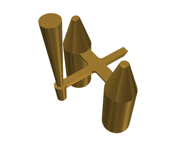
Figure 2. Rigging Drawing
I started by knocking up the mould as shown in the following photographs.
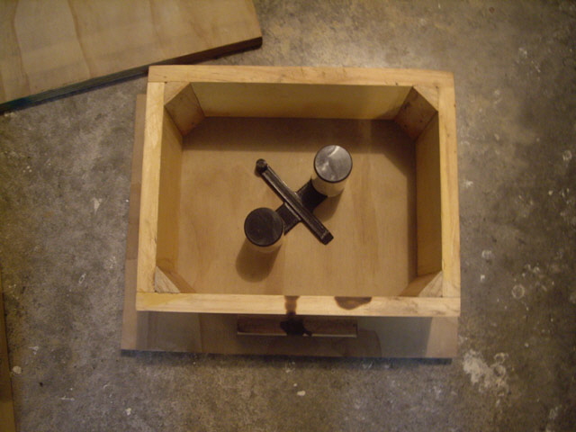
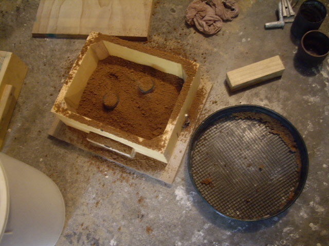
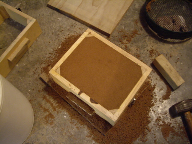
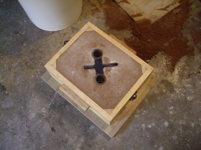
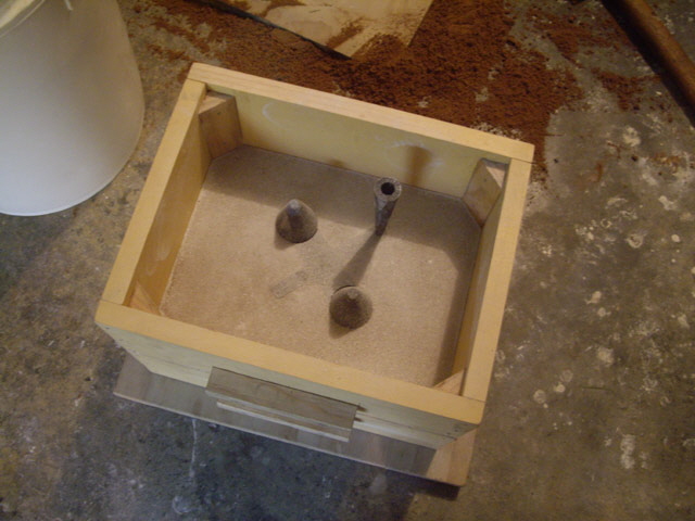
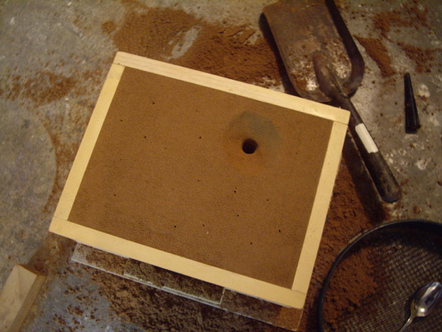
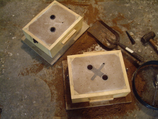
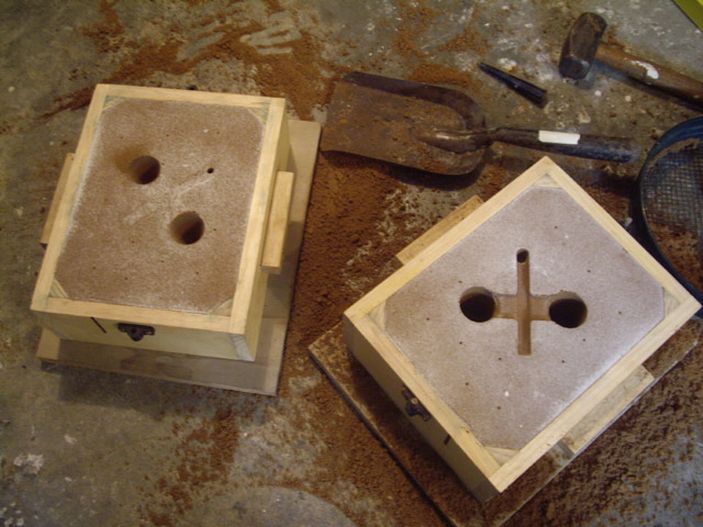
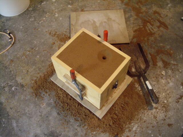
Figures 3a to i. Knocking up the Mould
With the mould made I measured 2.230 kg of brass for the melt. This was off cuts, swarf, the remnants of my first brass casting effort, and a few broken plumbing fittings that I have collected over time.
The furnace was lit and the initial charge (mainly the swarf) started to melt after just 10 minutes. Adding the remainder of the charge took an age because the crucible filled to capacity and I had to wait until the material had melted before I could add more. Half way through the melt (after about 30 minutes) I did an initial dross removal.
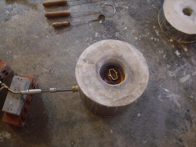
Figure 4. Crucible Charged and Burner Lit
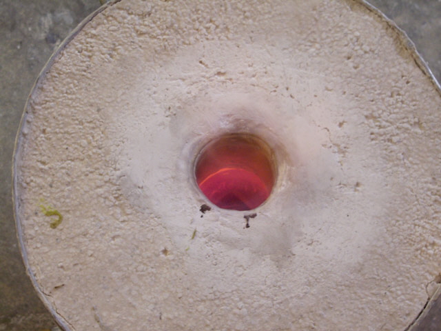
Figure 5. Charge Melting
After 50 minutes the charge was complete and molten. I wrapped 28 g of zinc from two old battery cases and immersed them in the melt to replace oxidized zinc. Next I added about 4 g of aluminium as an oxygen degasser. It flared spectacularly when immersed (burning brilliant white like magnesium ribbon). This was followed by a quick stir and dross removal.
The pour time actually took about 5 seconds but I didn’t have enough metal to actually fill the mould (a short pour). If I’m lucky the risers will have at least partially filled.
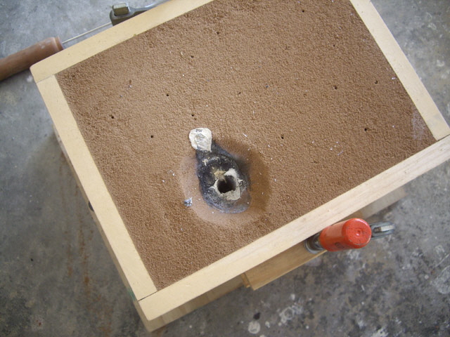
Figure 6. About 5 Seconds to Pour
After half an hour I broke open the flask. The metal was still very hot (> 100°C). The castings are much better than my first effort even though the risers hadn’t filled at all. The sink marks at the top of the casting were central and circular with a depth of about 25 mm. There was only the slightest hint of condensed zinc on the exterior of the castings. The surface finish wasn’t too bad, and was generally better at the top of the castings than the bottom. Some 3D printing lines were evident (about 0.2 mm deep).
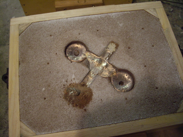
Figure 7. Flask Open after 30 Minutes
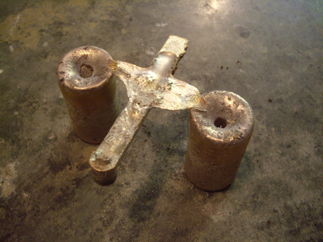
Figure 8. Casting
I trimmed off about 25 mm from the top of the castings with a hacksaw and sure enough I was right at the bottom of the sinks.
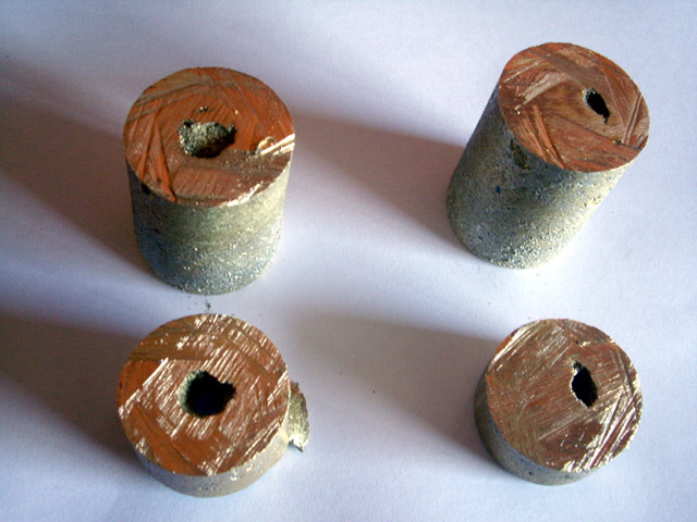
Figure 9. Shrink Holes Removed
I’m interested to understand why I have ended up with a short pour. I should have seen this coming as the crucible was only two thirds full, evidenced by the nice shiny brass plating remaining inside the crucible after the pour.
I measured the actual weight of the castings and rigging as cast at 1.589 kg so I had lost about 30% of the charge as dross! The reasons for this were probably the excessive melt time (about 50 minutes mainly because of the time required to add more metal without over-filling the crucible) and so much swarf in the charge. Swarf makes for a relatively large surface area to volume ratio undoubtedly increasing the propensity for oxidation and also limiting the capacity of the crucible during the melt.
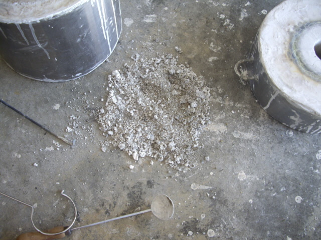
Figure 10. Dross
I know that some of zinc burnt off. Zinc burns with a very pretty blue/white flame which was evident in the initial dross removal. I removed a lot of dross and it was quite heavy. Unlike my first brass casting the dross was dark gray implying a mixture of black copper oxide and white zinc oxide.
The height of the cylinder pattern with the end caps fitted was 10 mm greater than designed. I thought that this increased volume would be filled by with the design 2.25 kg charge but it added 12.5% to the pour shortfall.
Brass Composition
I’m also interested to determine the cast alloy composition (and how much zinc I have lost). We can use the story of Archimedes and the Golden Crown to figure out the composition of the brass as cast. I weighed the two useful (solid) brass castings at 1.058 kg. I tried putting them in water to measure their combined volume but the scale on my improvised measuring cylinder (a graduated kitchen jug) was too course for meaningful results. However the useful castings are pretty much cylindrical with an average diameter of about 39.7 mm and average heights of 54 and 49 mm.
The volume of brass is therefore:
pi * 39.72 / 4 * (54 + 49) = 127.5 cm3
and the density is:
1,058 g / 127.3 cm3 = 8.3 g cm3
Given that the density of copper is 8.96 g/cm3 and zinc is 7.13 g/cm3 we can work out the copper composition by percentage weight as:
(Measured density – Density of Zinc) / (Copper density – Zinc Density)
(8.3 g/cm3 – 7.13 g/cm3) / (8.96 g/cm3 – 7.13 g/cm3)
So we still have pretty much 65/35 yellow brass.
While the pour time was about 5 seconds, this is reasonable given the reduced charge and the fact that the pour was largely directed straight into the top of the sprue. The metal flow rate in the rigging (based on the dimensions of the runner at 10 mm wide x 8 mm deep) was almost certainly below the critical flow rate of 500 mm/s:
1,589 g / (0.0083 g/mm3 * 8 mm * 10 mm * 5 s)
= 478 mm/s
There are a few observations about the rigging that are worth noting.
The sprue well was almost certainly choked during the pour as evidenced by it being full at the end of the pour.
The runner and gates weren’t completely filled at the end of the pour. I suspect that they must have filled during the pour by the condition of the sand in the cope and the full riser trap. They only drained into the casting at the end of the pour.
The runner trap was full of metal but there was no discernable dross or inclusions at the end. I figure that the charge was relatively clean.
The residual metal in the gates looked nice and clean.
The shrink holes at the top of the casting suggest that our risers would have worked well with a significant improvement in overall casting efficiency over my first brass casting experiment.
The surface finish is not ideal but is better than my initial brass casting attempt. I figure that this will clean up perfectly with a 1 mm cut. Given that the surface finish is significantly better at the top of the castings than the bottom I figure that this is due to turbulence caused by the height-drop between the gate and the base of the pattern. I suspect that molten brass may have actually sprayed from the gate into the casting cavity before falling to the base. This undoubtedly resulted in turbulence and probably disturbed some of the sand. The best solution to this is probably to have the gates no more than 25 mm from the base of the casting. This might have been avoided if I’d placed the patterns to have minimum overall height (one of the rules that I chose to ignore).
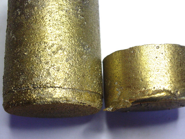
Figure 11. Surface Finish
(left: base of casting, right: top of casting)
At this stage it is timely to think about what I set out to achieve – and what I actually got.
I wanted a systematic rigging calculation and while the castings were not perfect, I have a basis from which I can refine the process in future.
The risers didn’t fill but the shrink on the closed patterns suggests that they would have worked.
The composition of the brass has remained about 65/35 copper to zinc with the addition of 28 g of zinc.
The pour time was faster than anticipated due to insufficient metal and possibly due to poor pouring technique.
Metal flow rate through the rigging was below the critical flow velocity.
The short pour was caused by too much dross formation as a result of too muck swarf in the charge and a protracted melting time.
At the end of the casting I have two useful pieces of brass stock about 50 mm long and 40 mm in diameter and, and three relatively clean and solid pieces of brass ready for the next melt.
The 25 mm long shrink hole off-cuts have actually proven to be useful. I have recently used one of the shrink hole offcuts for making a replacement cross slide lead nut for my lathe. With the shrink hole bored out the off cut was free cutting with nice clean chips and with no apparent inclusions, voids or fractures.
|