|
If you have got to this page then chances are you are having print failures or quality issues. You might also like to look through my other M2 pages that also discuss techniques for improving your prints.
Thin Wall Distortion Near Bed
I’ve been trying to print some prototype PLA parts for the Amigo case. These need to be a good quality print because they are being used to test assembly, form and function. The default M2 settings were causing distortion issues with thin wall sections near the bed, even when printed on a raft.
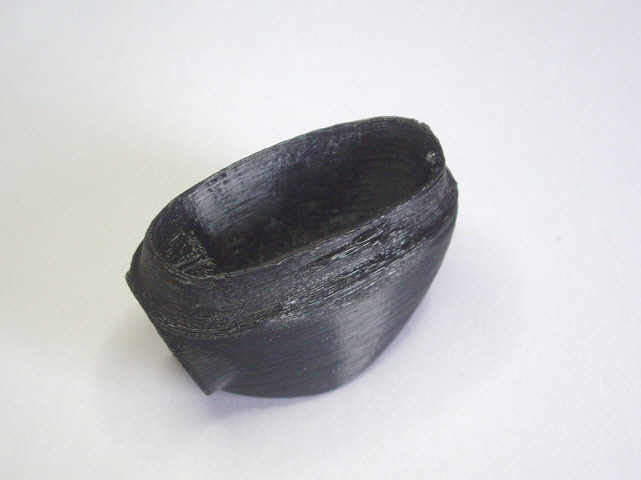
Figure 1. Thin Wall Distortion Near Base of Print
My first attempt at a solution was to increase support in these areas by adding manual support structures in Simplify 3D. This did improve things however it did not resolve the problem. The solution was to lower the M2 heated bed temperature from the default value of 70°C down to 65°C. The new setting still provided excellent bed adhesion while virtually eliminating the thin wall distortion.
- Thin wall distortion near the bed may be corrected by reducing the heated bed temperature.
- Change the print orientation of the part.
- Add Additional Supporting Structures.
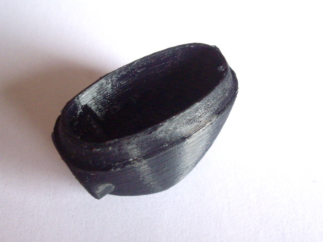
Figure 2. Improved Print by Reducing Heated Bed Temperature
Echoes from Embossed Text
The next issue that I faced with the Amigo prototype cases were echoes extending from external embossed text. These always occurred down-stream (relative to extruder motion) of sharp changes in direction. The echoes are very small deflections on the surface extending perhaps as much as 10 mm from the change in direction, with decreasing depth. They are caused by damped mechanical vibration of the X and Y drives following fast changes in direction.
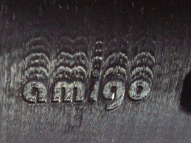
Figure 3. Echoes with Embossed Text (0.2 mm deep)
While echoes are very shallow and can be readily removed by sanding and solvent vapour sealing this does not fix the fundamental problem. Here are some tips:
- Make sure the belts are in good order and correctly tensioned. Clean and lubricate the linear rails. Examine and resolve any perceivable slop in the X and Y mechanical drives.
- Reduce the outer layer print speed in Simplify 3D down from the 60% default to say 20%.
- Experiment with the GCode acceleration and jerk settings (M204 and M205 commands).
- Change the design of the part using fillets to eliminate sudden external direction changes.
Banding Ripples on Vertical Walls
You may experience banding ripples on either the X, Y or X and Y axis, particularly after any machine adjustments. This may be a symptom of inadequate drive belt tension. The ripples will appear on walls that are perpendicular to the loose belt.
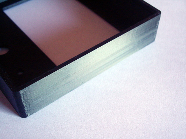
Figure 4. Clean Wall Parallel to Y Axis. X Belt Tension is Fine
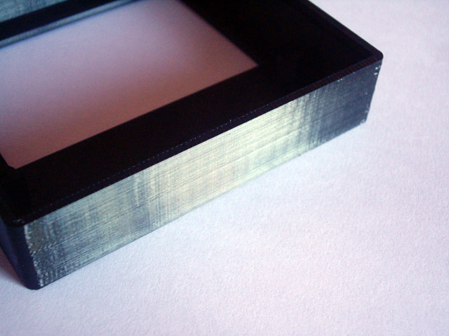
Figure 5. Banding Ripples Parallel to X Axis. Y Belt Needs Tensioning
To Increase the tension slacken the appropriate four motor mounting bolts. Press the motor using thumb-pressure to tension the belt and tighten the motor mount screws. Note that too much tension will result in belt stretch and undue wear of the motor and idler bearings. Do not use a lever. The correct tension is achieved when banding ripples disappear. A ready measure of tension can be made by moving the axis extruder motor to the end stop and pressing with your index finger in the centre of the exposed belt. With moderate pressure the belt should deflect to almost touch the return side of the belt.
Adequate Support Structures
3D printing requires that each layer is supported by the layers beneath or support structures. The surface finish of horizontal layers printed above support structures is not nearly as good as vertical walls, top layers or layers printed directly on the bed. This is because the printer separates the support structures from the finished part by typically one vertical layer and the support structures are printed as adjacent thin walls to allow for easy removal. In the first instance try and orientate the part to make the base of the print one or more large flat sections. But also remember that you don’t need to settle for auto-generated support structures. You can model your own provided that you provide at least one horizontal print layer clearance. The part will still separate from the support with minimal effort and the surface finish will be improved. This technique is particularly useful when a part has no obvious flat faces for the base, or requires a particular orientation to optimize visible surfaces. Adding a raft may improve print adhesion to the bed but it won’t help with print quality on the lower surfaces.
The following figure shows a part with no flat surfaces and deep recesses from the top and the bottom. Best print results were obtained by adding a modeled support structure.
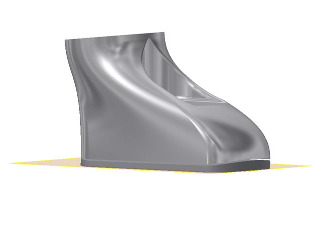
Figure 6. Modeled Support Structure
(Lower gray material is separated from the part by 0.2 mm.)
Click here to navigate to extruder failure...
|