|
Numerical Control (NC) models are a G Code file that controls the CNC machine to actually machine the desired part. I’ve been working on the tool path optimization for my very first production job with my new CNC mill, and experimenting with efficient mounting of the stock to a sacrificial bed.
The general process is to design the part in AutoDesk Inventor, Import the part into AutoDesk Fusion 360, generate the tool path, and export this as G Code for Mach3. Designing the part is using Inventor (or your preferred package) is something that I can’t reasonably cover on this site (it can take years to become proficient at this). But in designing the part you do need to be aware of the capabilities of your machine, and in particular axial constraints. It is pointless designing a part that you cannot reasonably machine.
Fusion 360 also allows for part design although I have not used this aspect of the software. I am already sufficiently well versed in Inventor, Autocad and Blender so I probably won’t need to revert to design in Fusion 360.
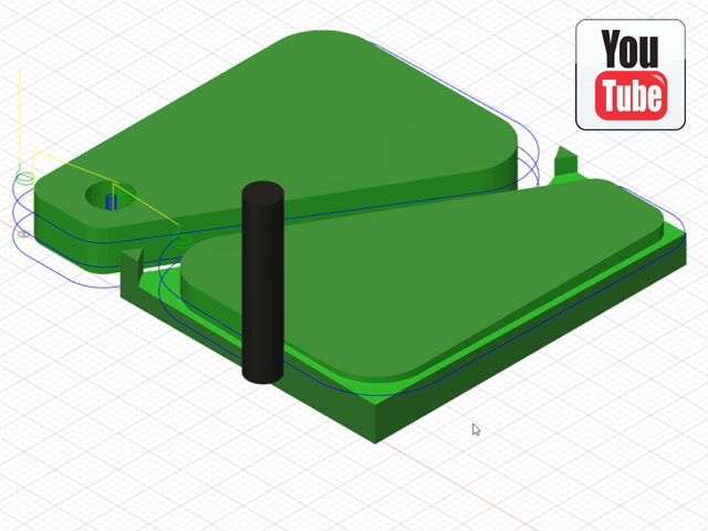
I’m no expert with Fusion 360, but I have reduced the time for milling of the side plates for my honing guide to 1 minute and 48 seconds per set using optimum cutting speeds and feeds for aluminium alloy for a 3/16” carbide end mill. The same job on my toy CNC mill took almost 48 minutes and the finish was far from satisfactory.

Figure 1. Almost Optimized Tool Path
While I have yet to actually run the mill I have simulated the job on Mach3. It simulates quite slowly at about 8 minutes because I have yet to load the USB plug-in and download the driver from the controller card and the stepper motor tuning hasn’t been completed. As a consequence Mach3 is attempting to run via a parallel port with a maximum frequency of 250 kHz (an unlicensed limit) which is too slow for the axial drives. The X,Y and Z axes on the mill are capable of speeds up to 4 m/min and the rotary axis will turn at 50 degrees/min. This speed problem will be resolved once the USB is configured and connected.
Tool Path and Mach3 Parameter Adjustments
With the CNC mill following a tool path under Mach3 it was time to optimize the model for efficient machining. Fusion 360 just wouldn’t let me define the tool paths that I wanted so I’ve ended up making a composite numerical control file from two slightly different models. This ensures that paths are pretty much optimized and the machining is done in an appropriate order to maximize stock stability and hole accuracy. The machining order is holes roughed, holes finished, profiles roughed, and finally profiles finished. The X and Y finishing feed rates were reduced from 3,400 mm/min to 1,700 mm/min.
The actual machining time was still too slow on the helically ramped holes. The issue is with the Mach3 stepper motor acceleration parameters which were set at 133 mm/s2. I increased these parameters to 1,000 mm/s2 which reduced the machining time to well under under 2 minutes. But this acceleration was too fast resulting in machine judder, even though there were no skipped motor steps apparent. So I adjusted the stepper motor accelerations back down to 400 mm/s2 which eliminates judder and provides an actual machining time of about 2 minutes and 20 seconds for my two part model.
Note that at 400 mm/s2 the axes accelerate to the maximum traverse speed of 4 m/min (66.7 mm/s) in just under 0.17 seconds.

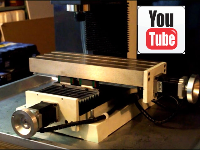
Figure 2. New Tool Path with Stepper Motor Acceleration Adjusted in Mach3
(Click on Image for YouTube video link)
After my first attempt at actual machining there is a significant issue with the helical plunge rate for the holes using a four flute end mill. These just don’t plunge well, except perhaps with a very low helix angle of say 2 degrees. The solution is to change the tool to a three flue end mill or a two flue slot drill as these plunge cut quite adequately. The tool diameter also needs to reduced from 3/16” to between 60 and 80 percent of the holes diameter to allow for swarf clearance.
Note that I could use a spot drill and drill bit but there are three different hole diameters in this job and this means lots of tool changes, or reverting to a jig and batching the job. An appropriate end mill should deal to all of the holes without changing tools.
A change in tool requires re-generating the tool path in Fusion 360 to suit the new tool and provide optimum surface cutting speeds and chip loading.
Click here to link to Electrical.
|