|
Don’t you just hate it when stuff breaks or wears out for no apparent reason? The LCD display on my NAD C520 compact disk player has become unreadable. The audio and CD deck are operating fine but using the unit without a legible display is difficult.

Figure 1. NAD C 520
If you look at the LCD under the right external lighting you can see that the basic LCD display is still functioning so the backlight has died for some reason.
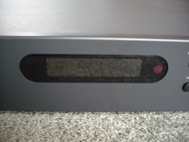
Figure 2. “no dISC” Display Hardly Visible
This machine is somewhat more complicated than a toaster so the the first thing to do is try and find a schematic diagram and some service information - otherwise you will spend an age tracing out the schematic for the backlight circuit by hand.
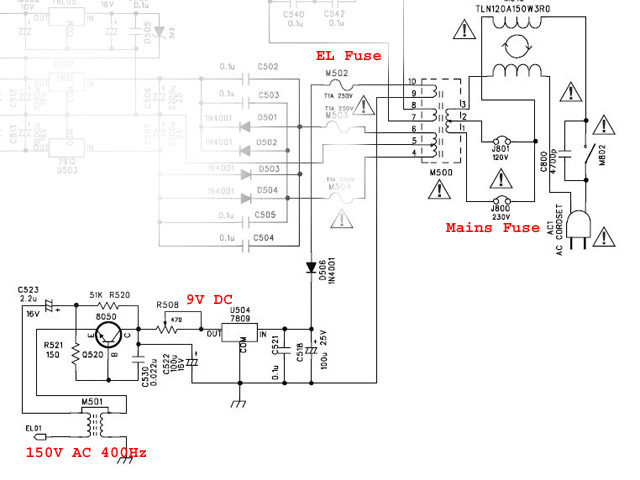
Figure 3. EL Backlight Circuit Diagram
The first thing I discovered from an Internet search was that the backlight is an electroluminescent (EL) panel and that these have a limited service life of perhaps 3,500 hours. It appears that many folk have had similar problems. I also found a copy of the service manual with a schematic, a fault diagram (which won’t help with this particular problem), board layouts and component identification.
I started servicing by removing the five case screws and lifting the case top clear (lift at the rear of the case and slide backwards).
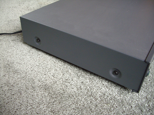
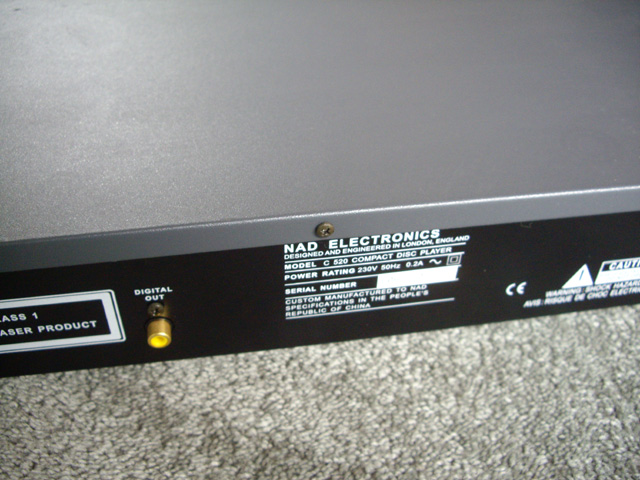
Figures 4a and b. Case Screws
Then I checked the EL backlight power supply starting at the AC fuse and progressively working through the rectifier and regulator to the EL high voltage AC test socket. You can do these checks with a simple multimeter (just keep yourself physically well-away from the mains supply on the AC power board).
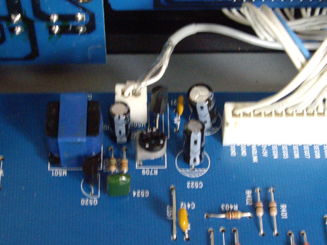
Figure 5. EL Drive Circuit and Connector
The actual EL output voltage isn’t specified in the service manual but the inverter is switching regulated 9 V DC through a 5:85 turns ratio transformer so under no load we should see about 150 V AC at the output terminal, adjustable through a variable current-limiting potentiometer. This estimate of the drive voltage seems typical of EL panels, with a frequency of around 400 Hz.
If you must tweak the potentiometer (R708) then tweak it right back to its factory set position because we have insufficient information to reset it. I figure that the factory setting is better than my guessing at the correct drive voltage for the EL backlight.
Okay the EL backlight power supply was fine with a voltage of around 180 V under no-load and 100 V with the EL backlight connected. The EL backlight panel has clearly died.
My next mission was to contact the local NAD service agent and inquire about a replacement LCD board. Pulling an LCD module to bits to replace a bonded backlight involves a lot of desoldering with significant risk of damaging the display. The technician I spoke to was exceptionally helpful and advised that it was possible to replace the EL backlight without removing the LCD display from the board. The backlight termination’s should be de-soldered very carefully with minimal heat and the replacement should simply slide under the LCD display module. I ordered a replacement EL backlight at a cost of about $30 which was available for pickup in just two days!
NAD and my service agent should receive full credit for this helpful response and the availability of spares. Sure the EL backlight has died due to a limitation of the technology in the design but they told me how to fix it and they have spares readily available at a reasonable price.
The Repair
Warnings. If you are uncomfortable with the prospect of damaging your CD player, soldering, or delicate manipulation then take you unit in to a bona fide NAD repair agency for service. If you decide to complete the repair yourself then keep your tools and hands clean (or wear disposable medical gloves), protect the LCD display from hard surfaces with a sheet of sponge and avoid any impacting the LCD with your tools. If you chip, crack or impact the LCD you will probably need to get a replacement LCD board.
Remove the power by unplugging the unit.
Disconnect the three LCD plugs from the main printed circuit board by carefully prying at the connectors with a fine wide-bladed screwdriver. Don’t pull on the cables or you’ll be trying to fix these too. Note the plug orientation for correct reassembly. Remove the LCD display board by unscrewing the three mounting screws (top left and right and bottom middle).

Figure 6. LCD Board Mounting Screws
Use a magnetic screwdriver to stop the screws ending up in the CD mechanism. I use an ordinary steel screw driver with an old hard drive magnet on the shaft for this purpose.
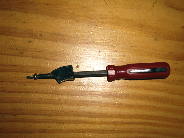
Figure 7. Magnetic Screwdriver
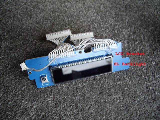
Figure 8. LCD Board Removed
With the LCD board on the test bench desolder the EL panel connectors and the LCD corner mounting bracket at the EL connector end with solder braid. You want to get rid of all excess solder. Then either gently pull the EL backlight connectors through the board or cut them with fine side cutters taking care to avoid any contact with the LCD module. Straighten the tabs on the LCD mounting bracket on the underside of the board and gently pull this from the top of the board.
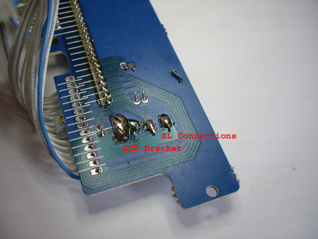
Figure 9. Desolder the EL Backlight and LCD Bracket Connections
Carefully slide the defective EL backlight unit and light mask from beneath the LCD display, noting that the pink side is up, and the orientation of the light mask (broad vertical strip at the bottom of the display).
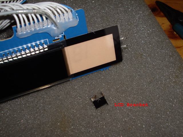
Figure 10. Slide Out the EL Backlight and the Light Mask
Your new EL backlight does not come fitted with non-conductive spacers and the old ones will be almost impossible to remove in one piece. I cut a strip of self-adhesive backed felt about 1 mm thick and put this on the back of the EL backlight.
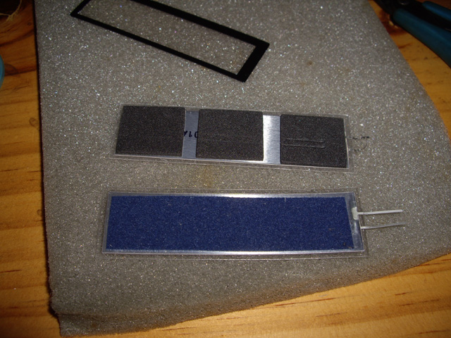
Figure 11. Light Mask, Old EL and New EL with Blue Insulation Fitted (top to bottom)
Now align the light mask on the pink side of your new EL backlight and gently slide them beneath the LCD display. If they appear to catch withdraw them a fraction and wiggle the EL backlight gently away from the LCD connectors while re-feeding. Do not force the EL backlight under any circumstances.
With the new EL backlight in place use tweezers to bend the ribbon leads and feed these through the circuit board mounting holes taking care not to strain the lead connections on the EL backlight. Solder the leads to the PCB and trim them to the PCB pads. Now refit the LCD bracket, gently bend the tabs and solder these to the mounting pad.
Refit and align the the LCD module using a magnetic screw driver to keep the three mounting screws under control. With plastic mounting bosses make sure to feel for the thread start by gently turning the screw anticlockwise until it drops.
Reattach the three LCD module plugs gently onto the main board making sure to check the polarity. There is not a great deal of support for the main board beneath these connectors so avoid excessive downward pressure.
Test that the display backlight is up and running by applying power before you refit the lid. If all is good (and it should be) disconnect the unit from the power.
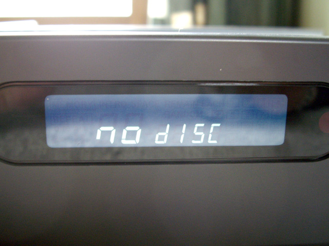
Figure 12. The LCD back in Action
Before you put the case lid back on you might carefully clean any dust from the CD unit and the the main board using a vacuum cleaner, avoiding significant suction on the CD unit. Don’t try to blow or brush any dust because it will invariably end up forced into places where it should not be (like in the CD optical path or the laser focal movement).
My CD player will live another day. I expect that next time the display dies CDs will have gone the way of the floppy disk and dinosaurs, and my NAD C 520 will be recycled to make a 3D printer.
|