|
I’m going to try and add a budget mist cooling and cutting fluid system to the mill to help keep work cool, improve machined surface finish, and preserve tool life.
Note that carbide tools don’t like sudden differential temperature changes. This can cause them to fail due to thermal shock. They either need continuous cooling or should be left dry.
I’ve ordered a stainless steel goose neck, two 12 V automotive windshield washer pumps (I only need one but they were so cheap that I’ve opted for a spare) and some soluble cutting oil. As is common experience for anyone with an automobile, the pumps should produce a nice low volume spray pattern with adequate head above the collection filter and tank without the need for an atomizing air supply.
The pumps are resistant to additives such as alcohols and detergents, and will run dry without damage (although they tend to make a horrible noise). While some of these pumps are not designed for continuous duty, this aspect of the design will be a trial. If this is a problem then I might try an automotive fuel or agricultural spray pump.
I anticipate having to experiment with the spray nozzle to get a desirable spray pattern with an appropriately low flow rate, but in any case the pumps should be good for flood cooling.
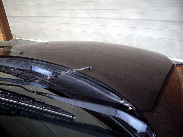
Figure 1. Winscreen Washer Spray
The pump needs a 12 V DC supply at say 5 A. While there is a 12 V DC/DC module in the control box this is not adequate for the load. A separate supply will be needed. I’m working on this.
I’ll also need to reconfigure the wiring in the control cabinet. The plan at this stage is to use one of the VFD relays to drive the spindle motor cooling pump contactor whenever the spindle is on, and use the existing relay for the spindle cooling motor (230 VAC) to drive the cutting fluid pump directly. This has the added advantage that the spindle motor cooling will always be on whenever the spindle motor is running.
The Schneider RXM2LB2JD relays that currently drive the contactors are rated at 5 A 250 VAC so they should be up to the misting pump duty (and the 12 V coils are already connected to the controller board).
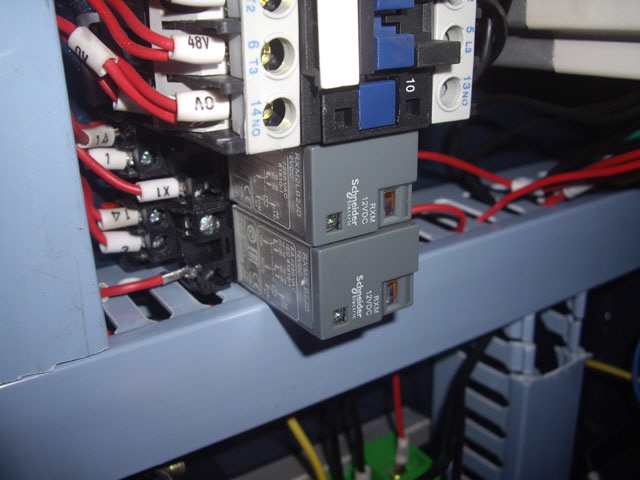
Figure 2. RXM2LB2JD Relays Rated at 5 A 250 VAC
The contactors are type CJX2 1210 but I haven’t got enough information yet to determine their configuration or drive voltage. I don’t think they’re a Schneider Electrical part because they place their logo on top of their contactors. I can’t see the label which is probably on the side between two adjacent units. If I can’t find the right date sheet then I’ll need to trace the existing wiring. This is more work in progress...
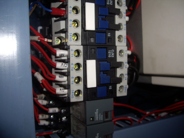
Figure 3. CJX2 1210 Contactor
(Specifications to be determined.)
Okay, I’ve finally got the specifications for the contactor by looking on the hidden sides for the switching terminations and drive voltage (230 V). After some more thought I have decided to replace the existing spindle motor contactor with a 10 A 250 VAC 12 V coil relay driven by the VFD. This frees up some space in the control cabinet and gives me a spare contactor. I’m also going to replace the existing relay with another 10 A 230 VAC relay. This provides rated switching of a 10 A 30 VDC load (the mist pump is a 12 DC 5 A device).
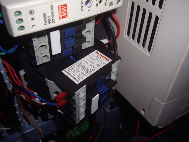
Figure 4. Contactor Termination Diagram
I’ve also purchased a 60 VA 230 to 9 V transformer as a simple full wave rectified 11.5 VDC (~12 VDC) supply for the cutting fluid pump, but after some thought I am going to replace the existing 48 to 12 V DC/DC converter with a 10 A device. I’ve already found another use for the transformer.
The parts for the upgrade are almost all here, except the cutting fluid pump and the new DC/DC converter. They aren’t far off. Before I can make the wiring changes I need a schematic diagram for the XK7113D (if for no other reason than being able to undo any changes). The process and the outcome are on the electrical page.
Cutting Fluid Drain
The cutting fluid needs to get from the tray through a swarf filter and back to the pump reservoir. So a drain and hose connection is needed for the tray. I designed and 3D printed the connector which is silicone sealed and fixed to the under side of the tray with three M4 bolts. While I could (and may eventually) print a rubber washer the Silicone RTV is quite adequate. The drain hose has a nominal 1/2” internal diameter. This should be fine for low-flow gravity-feed down to the reservoir. While 3D prints are porous they shouldn’t leak in this no-pressure application. Dimensional spacing is a bit tight due to the size of my tray. I should have made this larger.
I used a 3D printed template for drilling the drain holes accurately in the tray. The drain doesn’t protrude above the base of the tray and requires no metal forming (as typical of a sink drain). The sixteen 4 mm diameter drain holes provide ~200 sq mm of drainage which is about twice the sectional area of the hose. The 4 mm holes also provide the first level of swarf filtering. Anything that gets through these shouldn’t clog the hose, but in any case it is readily removed for clearing.
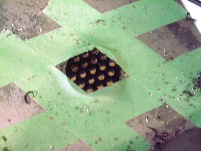
Figure 5. 3D Printed Template for Drain Holes
(Drilled to 4 mm diameter.)
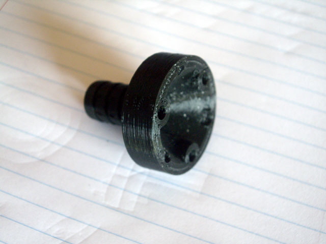
Figure 6. 3D Printed Drain and Hose Connector
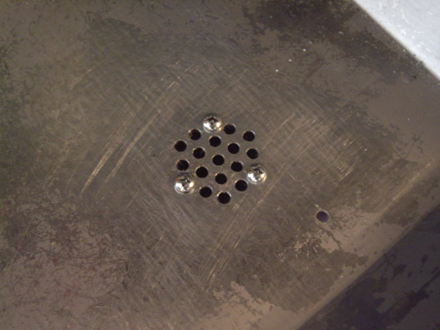
Figure 7. Completed Drain
(The hole to the right is for the machine guard.)
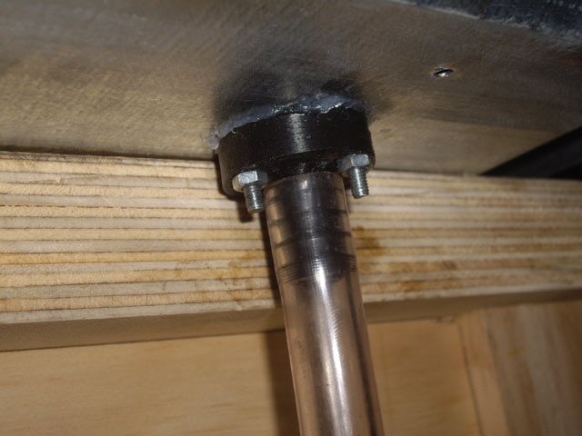
Figure 8. Drain Hose Connection
The cutting fluid in the tray should ideally be directed to flow towards the drain. While I could pack the tray or make Vee channels it will be easier to simply adjust the bench slightly off dead level, with the left-hand side say 0.5 mm above the right. The dead level tray capacity is about 0.4 litres per mm of of fluid height so I don’t anticipate having much cutting fluid sitting in the tray during use.
The pumps arrived today. I tested one of them on the bench (make that in the sink) with the spray nozzle. The motor current at 12 V DC with an open discharge tube is less than 1 A flowing 4 l/min. When the flow is restricted through the nozzle air intake (the larger port) the current increases to about 3.6 A and the pressure increases causing the hose push-on connections to leak (hey – we have a spray) and pop off. The pump is also quite noisy. The water jet is a solid stream. Flood cooling will be easy and will definitely clear swarf, but II want misting. And I need to make some more secure hose connections to finish my experiments.
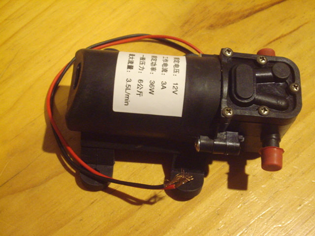
Figure 9. Cutting Fluid Pump
The pump is a double acting diaphragm type so it is positive displacement. The output pressure will keep on increasing until it is balanced by the flow rate; or the motor stalls or burns out; or the pipe, connections or pump fail. I don’t want stuff to fail and I want moderate pressure at quite a low flow rate for misting with a relatively light motor load. I think I can achieve this with a pressure switch (with hysteresis) and accumulator, or a regulated flow bypass circuit from the pump output, or an adjustable voltage regulator on the motor.
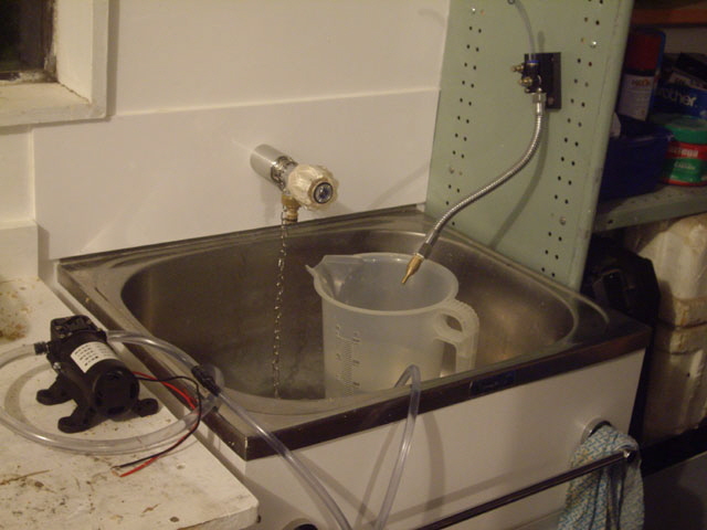
Figure 10. Initial Tests with Goose Neck
(I couldn’t photograph the discharge as I was too busy preventing leaks!)
If I’m going to get misting then I need to change the nozzle on my goose neck. The orifice on a standard trigger operated pump spray bottle or aerosol can produces good misting but the orifices are too small for adequate cooling flow.
My current stainless steel goose neck is designed to run on compressed air which draws the cutting fluid into the nozzle by a venturi. The only reason I purchased it was for the stainless steel goose neck. I fully anticipated modifying it. While the OEM nozzle has a relatively large 2 mm diameter orifice, there are a number of much smaller orifice plates inside that restrict the flow significantly, resulting in a relatively high output pressure from my pump, even with water pumped through the larger diameter air line.
The goose neck assembly was taken apart. We have an aluminium needle valve block with separate intakes for air and water, a plastic tube lined stainless steel goose neck, a central plastic water suction line, a brass adapter, a brass venturi, and the nozzle with the 2 mm diameter orifice. All of the threads were sealed with white silicone (which is pretty hard to clean off).
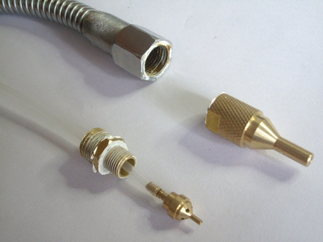
Figure 11. Goose Neck Nozzle Disassembled
I figure that if I remove the venturi and central line, turn down the nozzle a tad, and insert a 3D printed vane block to induce swirl, and then the nozzle might produce a filled-cone spray pattern at moderate pressure. Rather than machining the nozzle (which might ruin it) I thought I’d try replacing it with a 3D printed nozzle with integral swirl vanes that attaches directly to the goose neck. I can do this!
Here is my design. It is printed as a single component complete with a 19G Whitworth thread. It is entirely self-supporting so the printed part does not need support structures. If it ever blocks then it will be easy to print another one. It is difficult to envision the vanes that induce the swirl from the section so I have shown these separately. They are kind of like a single revolution auger or a twist drill with a profiled leading edge to reduce turbulence. This is the base design. I fully expect that it will need to be modified to achieve optimum flow, misting (or spray) and spray pattern. This will probably start with increasing the size of the orifice which is about 0.8 mm diameter as printed.
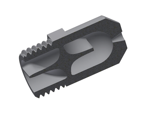
Figure 12. Vane and Swirl Chamber Design
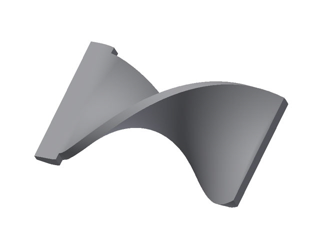
Figure 13. Vane Detail with Profiled Leading Edge
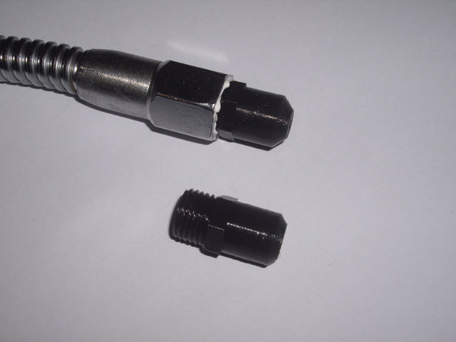
Figure 14. Two Variants of the 3D Printed Nozzle
I’ve started on my nozzle tests. The first problem I encountered was back-flow leakage through the unused needle valve even with the valve fully closed. I removed the valve. It has a 1/8” 28 TPI BSPT thread and I don’t have a plug on hand. I 3D printed one, but even with a high 50% infill and thick walls the pressure resulted in a constant water leak through the part. 3D prints are porous so I reprinted the part and solvent sealed it. It was fitted with Teflon thread tape (not messy silicon). No more leaks!
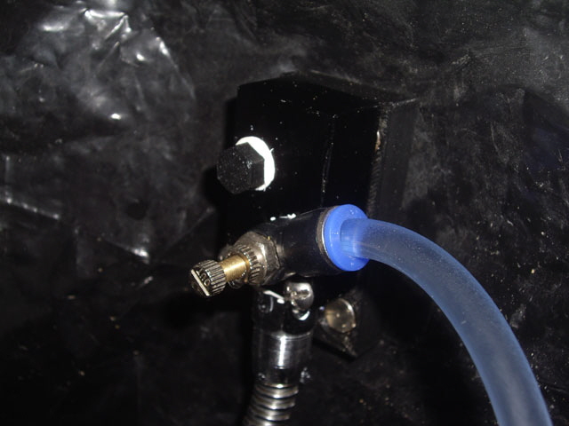
Figure 15. 3D Printed 1/8” BSPT Plug in Valve Block
(Solvent sealed for no leaks!)
The 0.8 mm diameter nozzle orifice is way too small resulting in very high pump output pressure which cause the tube connection to the pump to pop off resulting in water pumping all over the place. I drilled it out to 1.8 mm and reduced the pump voltage down to 6 V. This resulted in a good spray jet, although not quite a circular pattern, with appreciable misting. At the reduced voltage the pump is now relatively quiet and drawing about 1.9 A. The flow rate was measured at 0.4 l/min. The discharge velocity is calculated to be 2.7 m/s. The cone angle is ~15 degrees (almost identical to the 3D printed nozzle flare angle) which allows for good directional control and some peripheral wetting. This can readily increased by changing the flare angle on the printed part.
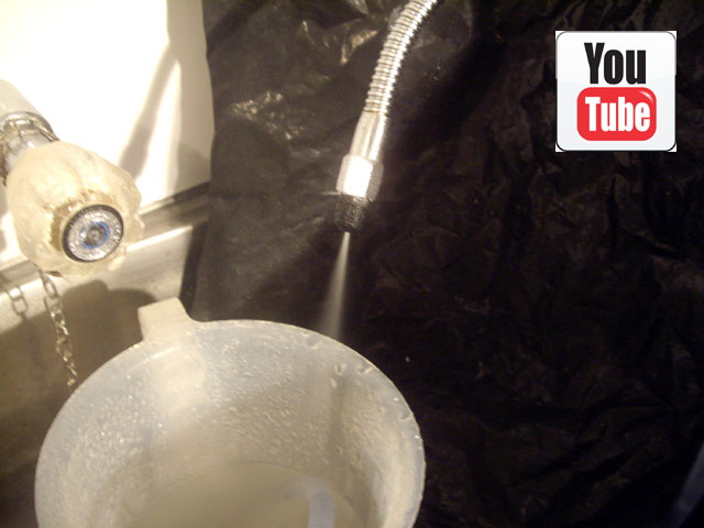
Figure 16. Misting Spray. Whoot!
(Click on Image for video.)
This jet will be quite adequate for the XK7113D CNC mill. It has enough pressure to blow swarf clear of the tool and stock, sufficient flow rate to keep stuff cool and lubricated, and an adequate discharge pattern (almost solid cone circular). I suspect that the non-ideal spray pattern is down to how I drilled the orifice out, simply twisting a drill bit between my fingers. I can probably do better than this by reprinting the part with the larger 1.8 mm diameter orifice. The 3D prints work so well that I won’t be modifying the OEM nozzle.
If a job needs flood cooling I figure I can make a new nozzle that will do this - no swirl, a longer nozzle, and a larger orifice, perhaps similar to the OEM part.
The 0.4 l/min flow rate will give me about 50 minutes of machining time from my 20 litre reservoir, and the drain should ensure effective return flow well before this.
A further consideration is what is going to get inadvertently wet (other than the tool, the stock and the bed). We have the X and Y stepper motor cables but these are relatively remote from the spindle chuck and are on the underside of the motors. I have also fitted homing switches but the Y axis switch is under a boot and the X axis switch is beneath the bed. In any case these switches are IP 68 rated so no problems are anticipated. But what about the potential for rust on the bed? Left standing the water in a soluble cutting fluid will evaporate leaving an oil film that should protect and lubricate metal surfaces and prevent water contact. So no issues are anticipated.
The last thing to sort out is how to regulate the cutting fluid flow. As mentioned above there are a number of options. I could run the pump from 12 V and add a valve-controlled bypass from the output back to the reservoir but this will result in increased pump noise and current. A simple 3 Ohm resistor in series with the motor should work but this will dissipate 12 W which means a physically large component. I’ve decided on a simple 6 V linear voltage regulator . The circuit is actually much smaller than a 12 W resistor and it will handle up to 40 W, cooled by the cutting fluid. The voltage is adjustable by changing out a singe low cost resistor.
Today I remade the goose neck block, and made the voltage regulator and the associated cooling block. The new goose neck block does away with the needle valves and significantly reduces the flow resistance. I’ve got a few more holes to drill and tap for mounting; and a new magnetic base and a cover for the electronics to 3D print, but we’re almost done.
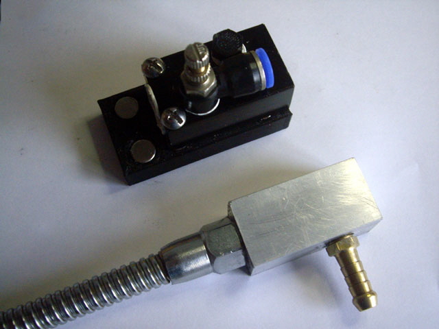
Figure 17. New Goose Neck Block
(Small than the OEM with significantly improved hydraulic performance.)
The voltage regulator design was designed based on an TL431 Zener. The circuit is capable of dissipating up to 40 W so it definitely needs the cutting-fluid cooled heat sink. The circuit was made from salvaged components (less the TL431) on a small piece of Vero board in about 30 minutes. It tested just fine with a stable output voltage of 6.01 V from open circuit to 1 A (about as far as I can push it without the heat sink). Note that using SMD devices would substantially reduce the size of the regulator.
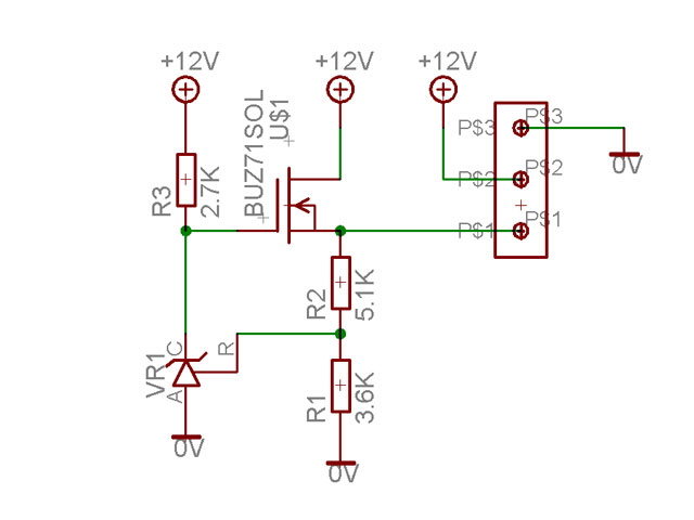
Figure 18. Simple 6 V 40 W Linear Regulator Design
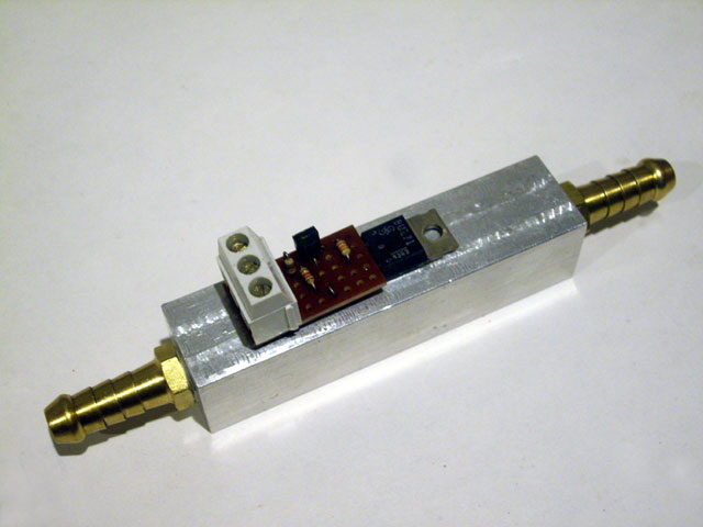
Figure 19. 6 V Linear Regulator on Cooling Block
(3D printed cover and mounting to follow.)
I’ve also been experimenting with my misting nozzles. I’m up to variant 5 and the spray pattern is improving and the current draw is decreasing with each iteration. The sweet spot for operating the pump is 6 V for almost no audible noise and a reasonable flow rate. Nozzle 5 with an orifice of 1.2 mm diameter draws just 1.5 A from 6 V and delivers 1.1 l/min in an almost circular solid cone. But it is more spray than mist. I need to reduce the orifice.
During my experiments with nozzles the spray went intermittent and then the pump suddenly stopped pumping even though the motor was spinning under no load.
I disassembled the pump and found an errant piece of red plastic (from the OEM assembly) in the cam drive and some debris (possibly sawdust?) preventing two of the spring loaded poppet valves from seating. I cleaned everything up and the pump is back in service. The nozzle also had some debris blocking the orifice. This looks like a piece of nylon from the goose neck lining and some of that nasty silicone sealant from the OEM build. I have 3D printed a fitting for a fine stainless steel mesh tap filter and put this on the intake line to try and prevent debris from blocking the poppet valves in the future. The remainder of the pump looks to be in good order with no undue wear apparent, an intact rubber diaphragm, and a serviceable motor.
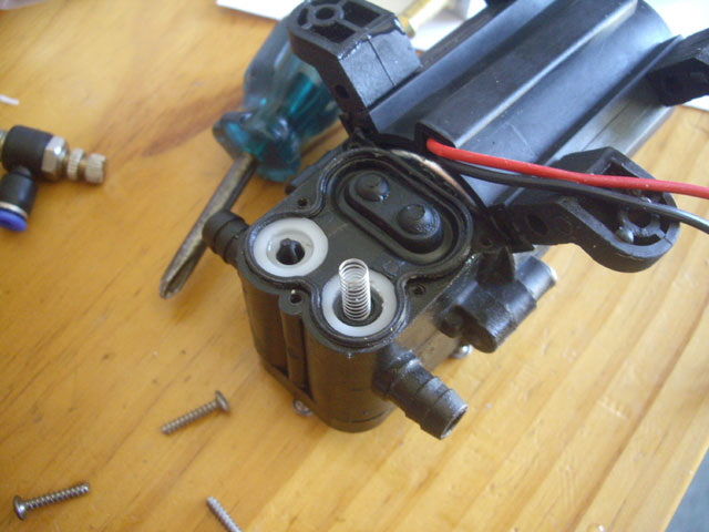
Figure 20. Pump Poppet Valves Not Seating due to Debris
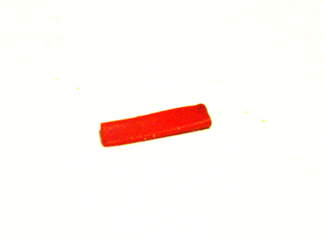
Figure 21. Errant Piece of Plastic in Cam Drive from OEM Build
(About 13 mm long)
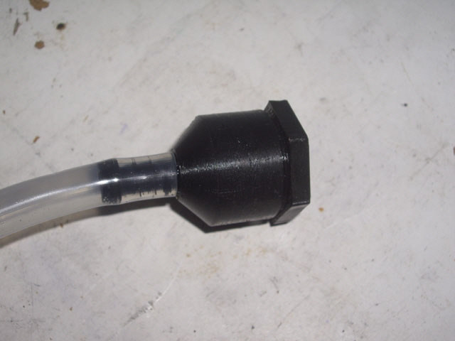
Figure 22. Push On Intake Filter
I’ll be printing nozzle variant 6 with improved profile removable swirl vanes and a slightly smaller orifice tomorrow. The reason for making the vanes removable is for effective solvent smoothing and sealing. This reduces leakage through the nozzle walls, improves the surface finish which reduces hydraulic losses, and makes for a stronger part. While I’m 3D printing I’ve made a splash cover for the 6 V regulator. I was going to use machine screws to attach it to the aluminium body but the fit is secure without the screws and additional machining.
After extended testing of a number of 3D printed nozzles the discharge pattern is a fraction too unstable. I figure that the 3D print quality and strength aren’t quite up to the task. I’ve decided to machine a nozzle body with a precision orifice and fit a 3D printed swirl vane. First up I need to make some hex stock about 14 mm across the flats. I have some 11 mm hex stock but this is just too small for the 1/4” BSPT thread on the goose neck.
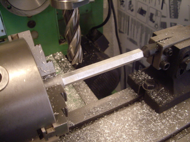
Figure 23. Making Aluminium Hex Stock
(14 mm across the flats.)
Next, machine a taper for the thread. BSPT is 1:16 or about 3.6 degrees.
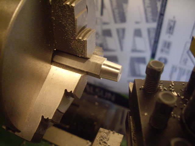
Figure 24. Taper Turning for the BSPT Thread
I cut the thread by hand using a 1/4” BSPT button die. With thin walled parts this operation is best done before drilling out the stock. I used the tail stock to keep the die square, and the tool post to support the die stock handle. The lathe chuck is turned over by hand using the chuck key. Easy in aluminium!
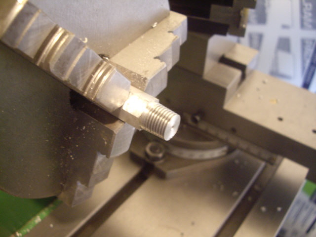
Figure 25. 1/4” BSPT Cut with a Button Die
Next I drilled the stock to a depth of 16 mm at 8 mm diameter, and over-drilled to a depth of 14 mm at 9 mm diameter to form an internal step to support the swirl vane insert.
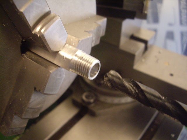
Figure 26. Over-Drilling to 9 mm Diameter
Now to work the orifice. Part and face the nozzle to an overall length of 22 mm. Spot drill. I used a 20 degree tungsten routing cutter to form the nozzle to a depth of 4 mm. Then I drilled an 0.5 mm diameter orifice through to the swirl chamber (about 2 mm deep) to complete the nozzle body. Then the external profile was adjusted by eye.
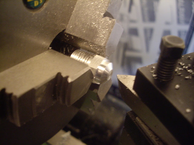
Figure 27. Forming the Nozzle
(I’ve got 2.5 mm to face off yet.)
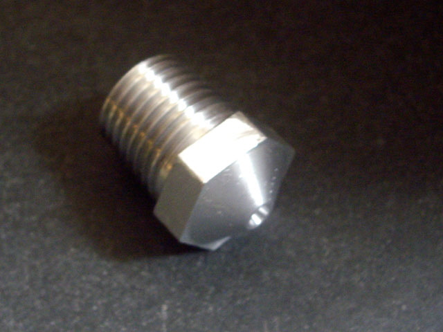
Figure 28. Completed Nozzle
I tested the new nozzle body without the swirl vanes. We have a nice steady solid thin stream of water with a flow rate of about 0.25 litres/min and a velocity of about 21 m/s. The motor is drawing 2.2 A at 6 V.
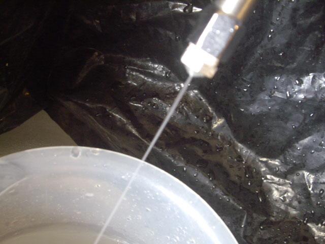
Figure 29. A Solid Jet from an 0.5 mm Orifice
The next task was to make some 3D printed swirl vanes. They’re a sliding fit into the nozzle body but the flow should keep them in position. I didn’t bother to solvent smooth these although the performance might be enhanced if I do.
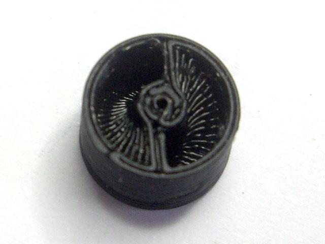
Figure 30. 3D Printed Swirl Vanes
(8.8 mm diameter for sliding fit into the nozzle body.)
The nozzle is now working beautifully with a 20 degree solid mist spray cone. The spray was completely stable over a 20 minute test. I expect that the spray mist characteristics will change slightly when I add the soluble cutting oil to the water, but this shouldn’t be a show-stopper.
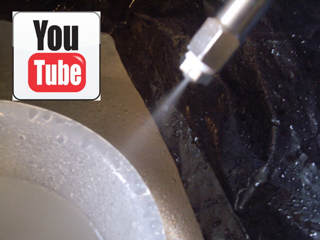
Figure 31. Fine Water Spray Mist
(Click on image for video.)
My next experiment was to added some cutting fluid concentrate (Rocol Multisol) to the water at the recommended ratio of 1:20. Interesting, the motor current decreased (down to 1.6 A) the flow rate dropped, and the pump developed a minor drip-leak somewhere on the bottom diaphragm cover. I figure that the increased fluid viscosity is causing the pump to reach its maximum pressure capability. I need to increase the orifice diameter a fraction to increase the flow and get the pressure down a tad.
I drilled out the orifice to 0.6 mm diameter (that’s a 44% increase in area over the original 0.5 mm), the flow rate returned to just under 0.5 litres/min and the pump leak stopped. The spray mist is back in the realms of what I am trying to achieve and the motor current is at 2 A. The spray velocity has actually increased up to about 30 m/s.
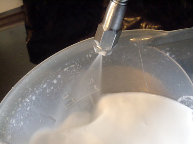
Figure 32. Soluble Oil Spray Mist
(0.6 mm diameter nozzle.)
There is quite a lot of misting happening, particularly from the jet impinging on stuff. It even managed to coat my camera lens which required cleaning. Having re-read the Multisol MSDS, misting may not be such a good thing . It is pretty much nasty with numerous hazards - skin and eye irritant, corrosive, toxic, ...
So I’m also going to make a flooding nozzle to stop the misting. I have some hexagonal aluminium now, but rather than machine this from scratch I got an old brass 1/4” BSPT hose tail fitting and cut off the hose tail at the first barb. It has a 3 mm orifice. Testing showed a solid stream with a flow rate of about 1.8 litres/min. I drilled out the orifice to 4.5 mm diameter to reduce the velocity a bit and the flood nozzle is complete with absolutely no mist or spray. The motor current dropped way back to 0.7 A with the flooding nozzle.
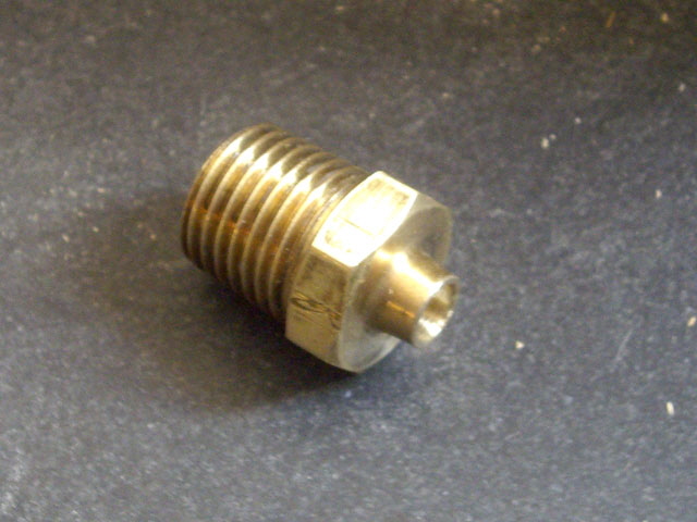
Figure 33. Flood Nozzle Made from Hose Tail Fitting
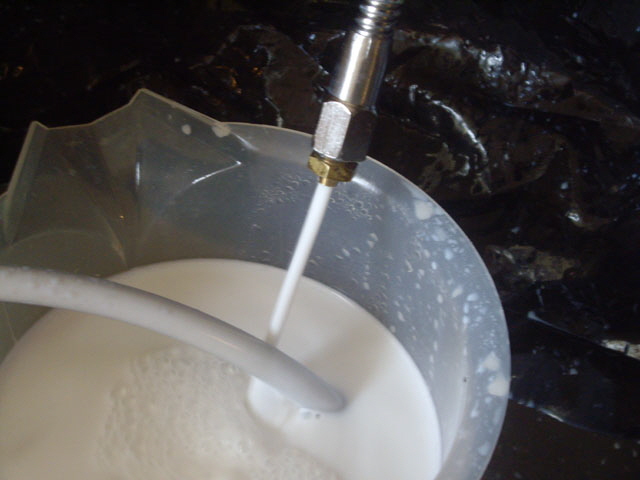
Figure 34. Flood Cutting Fluid Nozzle in Action
Okay, this part of the job is pretty much done. I’ve just got to mount the pump and regulator cooler on a board (marine ply, not MFD which will delaminate when wet), fill my 20 litre tank with cutting fluid, move the spray unit to the XK7113D mill, and wire it up to the 12 V terminals on the control box.
The pump and regulator cooling block are mounted on ply which sits on top of the tank lid. The lid acts as a tray in the event of any minor drips or spills.
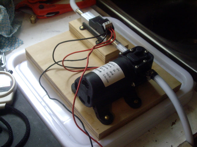
Figure 35. Pump Mounted Ply on Tank Lid
We’re almost done, but I have modified the regulator cooling block, moving it to the output side of the pump, incorporating two additional ports (one 1/8” and the other 1/4” BSPT) for a bleed return line and pressure gauge. This reduces the suction head of the pump, while making the pump unit footprint smaller.
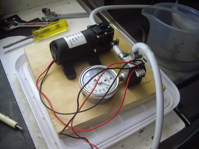
Figure 36. New Layout
The output pump pressure with the spray mist nozzle is about 470 kPa (68 psi). The pressure appeared to be relatively stable but after a few minutes it started to fluctuate rapidly. There are no blockages in the lines or filter - something weird is happening with the pump. There is an over-pressure relief valve between the outlet and inlet ports. From other manufactures literature this appears that this is rated at about 70 psi. This is too close to the observed operating pressure to be a coincidence. With the current 0.6 mm diameter nozzle orifice, and a reduction in the suction head of the new block, the over-pressure relief is probably operating almost continuously. I figure that the rapid pressure fluctuations are due to air in the pump.
I changed out the pump but the over-pressure relief on my spare (which has already had issues) isn’t working at all. The pressure keeps building up until the motor stalls. I’m going to strip down and rebuild the pumps. I figure that they just aren’t quite right for for this application. A micro gear pump that will run from 12 V with a flow rate of say 0.5 litres/min would be better.
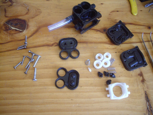
Figure 37. Pump Disassembled
The pumps appear to be serviceable. There seems to have been some issues with the poppet valve seats with flaking plastic, but otherwise everything looked okay. If necessary I will remake these using brass. Everything was cleaned and on reassembly I replaced the cam drive petroleum grease with Molybdenum. Interestingly this reduced the motor current by over 10% under no load. Both pumps are working again, flowing just on 2 litres a minute at 30 kPa from the flood nozzle with a 6 V supply at 0.732 ad 0.90 A respectively.
In order to prevent the pump internal over-pressure relief valve operating I’ve either got to install the bypass line or increase the nozzle orifice. Using two of my old 3D plastic nozzles the optimum orifice size was determined by trial and error to be 0.8 mm diameter with an operating pressure of about 410 kPa.
The spray misting nozzle was drilled out to 0.8 mm and we are back in business. The flow rate is about 0.75 litres/min with an almost constant pump output pressure of 410 kPa. This give me sufficient headroom for nozzle elevation changes at 10 kPa per vertical metre. The motor current is about 2.6 A from the 6 V regulator. The increased motor current (from the previous value of 2 A) is a sure sign that the over-pressure relief isn’t operating. The velocity is down from 30 to about 25 m/s but this is still more than adequate for removing swarf.
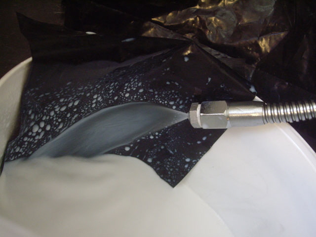
Figure 38. 0.8 mm Diameter Spray Misting Nozzle
(Impinging on black plastic sheet for contrast.)
I tried taking a flash photo to see if I could better characterize the spray but the flash just isn’t fast enough to freeze the spray. The bulk of the spray comprises small droplets but some misting is still occurring as can be seen from the condensing drops on the plastic sheet.
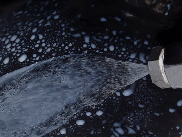
Figure 39. Flash Photo
I fitted the spray mist unit to the mill, leveled the tray for drainage and tested the unit. There were two problems. I had numerous leaks from the tray through the guard mounting holes and one of the mill mounting bolts. So I lifted the mill and reworked all of the mounting bolts to prevent further leakage using rubber washers and a compression nut. I’ve also removed the guards, cleaned the tray, and silicone sealed the guard mounting rails before re-bolting them to the tray.
The second issue was that the magnetic base just wasn’t quite strong enough to mount securely on the mill column. While it can’t be pulled straight off it can slide. I’ve modified the design incorporating two additional magnets and now it’s secure. While it will mount on the spindle using the column means that the hose is not being pulled up and down during milling.
Next up was to 3D print some fittings for the tank. One for the drain, on for the pump intake, and a third for a pump bypass. While I could have simply cut some slots in the tank wall for the hoses, this weakens the tank. These are all low pressure fittings so solvent-sealed 3D prints shouldn’t leak. The hoses are readily connected or disconnected, and the spray unit is readily portable to my lathe (although I’ll need to fit spray shields and a drain to the tray).
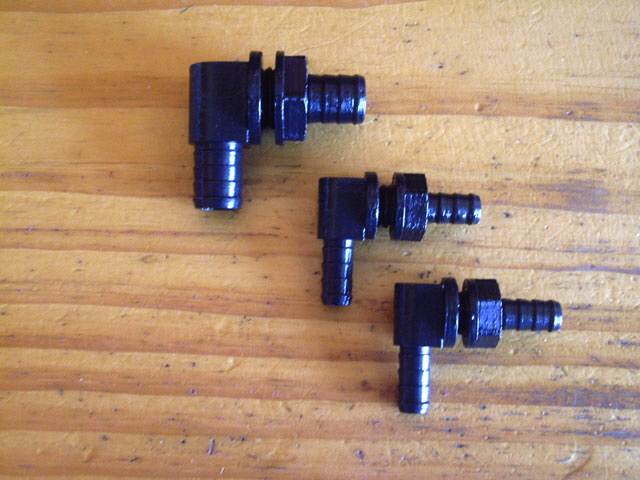
Figure 40. 3D Printed Tank Fittings
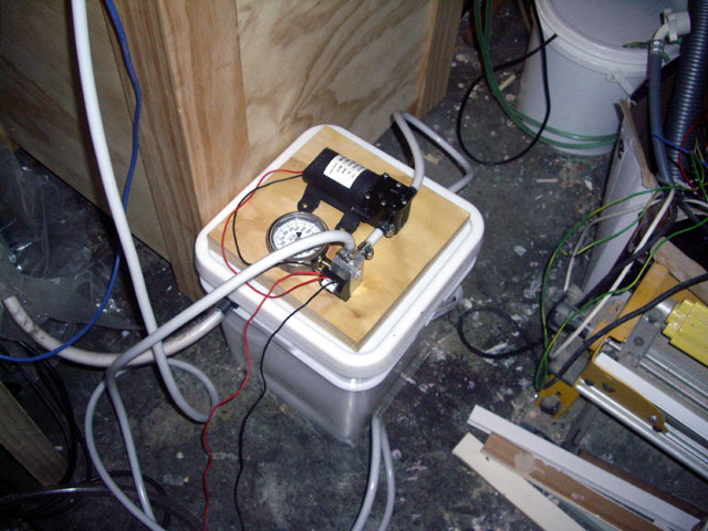
Figure 41. Pump on Tank
(I could probably trim the hoses a tad.)
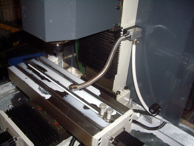
Figure 42. Goose Neck Attached to the Column on a Magnetic Base
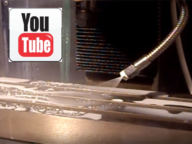
Figure 43. All Done
(Click on image for video.)
And the cost? I’ve look over the invoices and the cost including freight for things like the pumps, the goose neck, the new primary regulator and relay, tubing a tank and fittings was pretty close to US$75 all up. Other bits from stock, junk, 3D printing and the like probably came in at around $25 if I had to purchase these new. So we looking at about $100 plus time. I figure a commercial unit would have been close to ten times as much plus freight.
There was an additional cost for the BSPT taps and dies. These were close to US$100 but I didn’t actually need the 1/4” dies and I could have got these cheaper by shopping around and going for reduced freight fees (but at slower delivery).
Click here to link to the CNC Mill Parent Page (you’re at the last sub-page for now).
|