|
My M2 has an original borosilicate heated bed. The glass isn’t dead flat and from time to time I experience lifting of the edges of a 3D print off the bed or adhesion failure, particularly with parts near the edges of the bed.
There are several solutions to this problem: printing on a raft, using a level probed surface and adjusting the Z height dynamically in software based on probe mapping, or getting a flatter bed.
After some deliberation I have decided to splash out on a 1/4” thick 8” wide x 10” long MIC-6 aluminium plate bed. This should ensure more even heating and a flat printing surface. The modification should be very straight forward. Replace the glass with the plate, change out the bulldog clips to suit the thicker bed, level the bed and zero the Z axis. Other folk who have completed this upgrade have reported that this has resolved bed flatness issues (freeing up the entire surface of the bed for printing) and improved print adhesion.
If I have any issues with bed adhesion with the new plate then I’ll either put down a layer of Kapton tape, chemically etch, bead blast, or anodize the surface.
While the proof of this exercise will be in the performance we can estimate what improvements we might reasonably expect. This is all theory (and perhaps somewhat speculative). If you just want the details of how I carried out the upgrade click here.
Thermal Performance
With the exception of conductivity and thermal coefficient of expansion the thermo-physical properties of aluminium and borosilicate glass are quite similar:
|
Property
|
Glass
|
Aluminium
|
Units
|
|
Conductivity
|
1.14
|
205
|
W / (m K)
|
|
Density
|
2.23
|
2.7
|
g / cm^3
|
|
Heat Capacity
|
0.84
|
0.9
|
J /(g K)
|
|
Thermal Expansion Coefficient
|
33E-7
|
24E-6
|
1 / K
|
|
The original glass bed is about 3.7 mm thick and the MIC-6 plate is 6.3 mm thick. So we’ll have almost twice as much aluminium as by volume and weight as the OEM as glass bed. This shouldn’t be a problem for the Z axis motor which seems to have plenty of torque.
For a given bed heater wattage, the aluminium bed should take about twice as long to heat up. However aluminium is a significantly better thermal conductor than glass so it should heat up more evenly with less temperature variation throughout the plate, and it should stabilize significantly faster than glass. Note that the M2 printer the bed temperature thermistor is actually on the bed heater and not the glass bed.
Thermal Expansion
The difference in the thermal coefficient of expansion and plate thickness means that we can expect that the aluminium will expand about 10 times more than glass for a given change in temperature in every dimension. The critical dimension for the first print layer is the Z axis. But the actual increase in the bed height will be very small, particularly is comparison to the thermal expansion of a hot extruder nozzle at 220°C. Let’s assume that the bed temperature is increased from 20 to 70°C.
For the glass we have a Z change of:
and for te aluminium plate we have:
Changes in the X and Y dimensions should not be critical provided that the bed temperature has actually stabilized before we start the print.
So far we haven’t actually seen any significant advantages in the use of aluminium for the bed, but here is the first. The differences in temperature across a heated glass bed cause it to bend (deflect) more than the aluminium plate. Aluminium is such a superior thermal conductor that we can expect minimal temperature variations across the bed even though it is thicker than the glass.
The heated glass bed will tend to convex to the heat source. So it will deflect downward in the centre because it is supported at the corners whereas the aluminium plate should remain almost flat.
The extent of this bending is a difficult to calculate because we can’t predict the temperature distribution in the glass plate caused by bed heater. But thermal expansion and contraction forces are relatively large so we can make a ready estimate. Let’s assume that we have a temperature differential of say 10°C between the top and the bottom of our glass bed based on a 3 m/s forced air convection coefficient of 60 W / (m^2 K). The diagonal between the corners of the bed is nominally 12.8” or 325 mm but the cooler top diagonal will be less than the bottom of the plate by about:
The only way the glass bed can allow this induced strain is to deflect, with the edges bending upwards relative to the centre (concave like a saucer). We can estimate the deflection by assuming that the diagonal bends to form a circular arc, calculate the radius of the arc, and finally the sagitta (height) of the arc’s chord.
The relative vertical movement of the edges will be about 0.11 mm relative to the centre. This is certainly enough to cause print problems. Thermographs of glass heated beds show temperature variations of up to about 30 degrees on the upper surface of the plate due to the location of the heating element and significant cooling at the edges.
The aluminium plate, despite being appreciably thicker than the glass, will have an upper surface temperature very close to that of the bed heater once stabilized. With the same convection coefficient we can expect the upper surface temperature to be 69.9°C. Excluding the edges of the plate the temperature will be relatively constant over the entire upper surface of the heated plate. The increased length of the upper surface diagonal reduces to:
This is an order of magnitude less than for glass resulting in almost no deflection of the aluminium plate. The estimated maximum vertical deflection of the heated aluminium bed due to thermal expansion is about 0.005 mm.
Flatness
The flatness and thickness tolerances of the bed are also important considerations, noting that we can adjust out parallelism issues with bed levelling.
Unless glass is a ground and polished optically flat it is anticipated that it will have less dimensional accuracy than the machined aluminium tooling plate. For borosilicate float glass we can reasonably expect a flatness of 0.1 mm along the diagonal and a variation in thickness of +/-0.2 mm.
I can’t actually find a meaningful specification for the flatness of MIC 6 cast plate. However the thickness tolerance is about +/-0.1 mm which is a significantly tighter tolerance than for glass. Precision surface grinding operations can consistently produce a flatness of less than 0.02 mm, but this is subject to all manner of variables including the size of the ground plate, the type and condition of the grinder and operating variables.
So we can reasonably expect that an MIC6 aluminium heated bed will be flatter than a glass bed and will deflect significantly less when heated, even to moderate temperatures.
Part Adhesion and Release
Interestingly the thermal expansion of the aluminium is much closer to typical printing filaments than borosilicate glass. This is expected to affect both printed part adhesion and release. The majority of my 3D printed parts adhere surprising well to a clean heated glass bed and release readily when the bed cools. Given that the aluminium is expected to be flatter than the glass we may not achieve the same adhesion. If this is an issue then the bed will need to be coated with Kapton tape or roughened.
The X Y thermal expansion of aluminium is almost ten times more than that of glass but unfortunately it is almost identical to PLA. So if we get good adhesion we might struggle with part release, even on cooling. If this occurs then there are several methods that can help with the release (more force, heating and cooling and solvents including water). I’m not game to try a scraper or razor on the aluminium as this could easily scratch the soft aluminium bed. In an attempt to avoid this issue I’ll be reducing the bed temperature on my first trial prints by about 20 degrees.
MIC-6 Plate
The new plate has arrived in a relatively short time and in good order. While the packaging wasn’t the greatest, the plate seems to be undamaged (free from surface scratches or apparent bending).
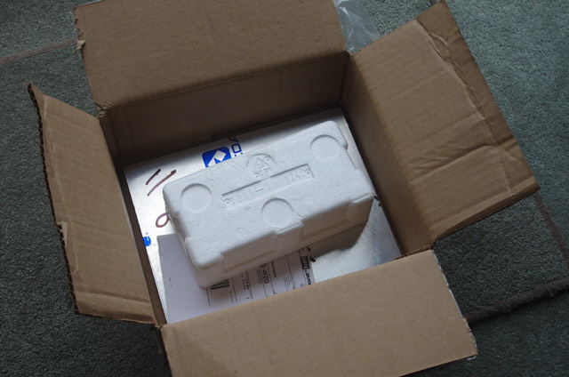
Figure 1. MIC-6 Packaging
Based on the plastic protective film I’m pretty confident that this is indeed aluminium tooling plate.
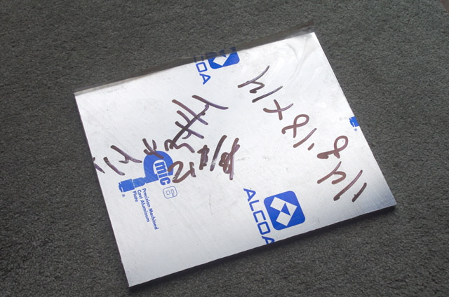
Figure 2. OEM Protective Film (both sides)
I figure that two edges of the plate have been cut with a circular saw based on machine marks. These are perpendicular, straight, and good enough for use. They were probably cut at the point of manufacture and are likely to be the original sheet edges. The remaining two edges look like they’ve been put through a band saw to cut my piece to size. These cuts are pretty rough and will need finishing.
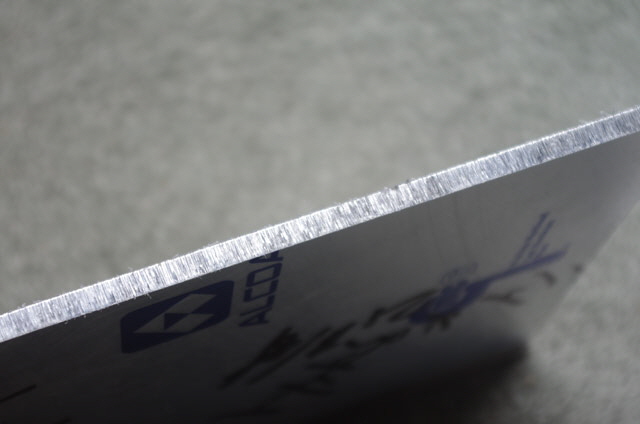
Figure 3. Rough Band Saw Cut Edge
The plate is fractionally large by about 5 mm in length and width. This is much better than being fractionally small, but a consequence is that the plate won’t fit in the current bed mounts. While I could remake the bed mounts or remove the excess metal by hand this will take a lot of time and effort. Best I mill the plate to exactly 10” x 8” and square. This has its own set of challenges for secure mounting as my mill won’t handle plate longer than about 9”.
Milling day! Rule number 1 is protect the plate surfaces. Aluminium is much softer than glass and could be readily damaged by a dropped tool or abrasive media. This means leaving the protective film in place throughout the milling. I used MDF as a base board and a clamp packer on to of the MIC-6 plate. Mounting everything secure wasn’t too much of a challenge. I have a standard rectangular hollow section steel block with arrays of mounting holes made just for this purpose.
In order to ensure dead square I an A4 sheet of 80 g/sq m paper template cut to size on a paper guillotine and taped true with the OEM cut sides.
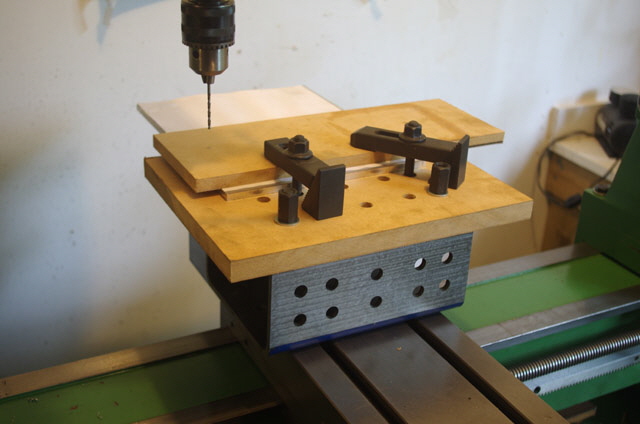
Figure 5. Clamped MIC-6 Plate for Side Milling to Size
Milling proceeded with the 8” side first. A 4 mm roughing cut was followed by re-alignment to ensure a square cut edge exactly on the edge of the paper and finished to size. The clamps needed to be repositioned during each cut for the full edge traverse. This was easily achieved by moving just one clamp at a time. The 10” side followed using a similar procedure, but flipping the plate to complete the cut and repositioning against small wooded blocks attached to the MFD base board with super glue.
The edges of the plate are sharp from machining. Working off a sheet of clean plywood I beveled these by hand with an 800 grit sanding block, working away from the flat faces. This was followed a solvent wipe away from the faces to remove sanding dust and swarf.
The protective surface film was removed and traces of remaining adhesive were cleaned off using a tissue soaked in isopropyl alcohol. There is a machine line on the underside of the plate about 5 mm from the OEM 10” cut edge, probably caused during the OEM cutting. I can feel this with a finger nail. The other side (previously covered with the Alcoa logo) is scratch free
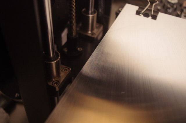
Figure 6. Fine Scratch Mark from OEM Cutting
(left hand side of bed)
Both sides of the plate show visual surface grinding patterns. I can feel the grinding marks with my finger running perpendicular to the pattern. Tactile perception is remarkably astute extending to as low as 10 nm (0.00001 mm). The Alcoa side has more pronounced machining marks based on feel, but it doesn’t have the scratch line. I’ll try this as my printing surface.
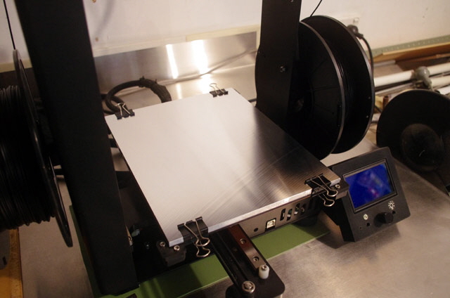
Figure 6. MIC-6 Bed in Position Alcoa Side Up
(Note the surface grinding pattern.)
The plate now fits the bed mounts perfectly. I changed out the existing spring clips for the next size up and the MIC-6 plate is now securely mounted.
The Z axis drive is absolutely fine despite the increased bed weight. Now all I need to do is level the bed and re-calibrate X, Y and Z and we should be good for 3D printing.
Initially I levelled the MIC-6 bed with the Alcoa logo side up. Note that stainless steel feeler gauges are much harder than the MIC-6 aluminium plate and may leave scratch marks. These are of no consequence as I can’t even feel them, but if necessary they will easily polish out. Scratches can be avoided entirely by using plastic feeler gauges or, for comparative measurement, a thin piece of plastic cut from an old container, but these are not adequate for hot Z calibration . Manual measurement of bed flatness from the tip of the left extruder gave a maximum deviation of 0.05 mm upwards along the Y axis centre line. While this is acceptable perhaps the other side will be even better?
I turned the plate over and positioned the scratch mark on the left hand side where it will almost never be used. The MIC-6 bed is almost dead flat across the upper surface (measured at less than 0.02 mm, the limits of my feeler gauges) relative to the extruder nozzle tips. This includes any variations in the X and Y axis linear rails. This should be more than adequate for a stable bed, and is somewhat better than old glass bed but I don’t have comparative measurements.
Note that while the M2E Z axis can produce relative movements of just 0.005 mm (1/8” pitch Z shaft, 40 pole motor and 16 bit micro-stepping), high resolution layers are typically 0.1 mm thick and the standard extruder nozzle diameter is 0.35 mm.
Next I heated the bed from 16 to 50°C. It took just over 4 minutes which is comparable to the borosilicate glass (20 to 70°C in about 7 minutes). I was expecting the new bed heating to take almost twice as long based on material properties and volumes but I figure that the new bed may have better thermal contact with the heating plate. Interestingly there were some creaking sounds during initial heating which I put down to thermal expansion. The entire bed remained flat within my feeler gauge tolerances.
I assessed the bed temperature by touch. I can’t feel any cold spots at all with this crude measurement but I fully expected that the new bed would heat evenly.
I still have to adjust the zero but while I’m about it I want to change the start sequence for the extrude purge and wipe to allow for the slightly larger bulldog clips and prevent early ooze on the bed.
With the bed level and calibrated its time to try some printing with a reduced bed temperature of 50°C. My test model is a simple rectangular block, 30 mm x 10 mm x 5 mm high, with 5 mm holes diameter at either end. The model is deliberately relatively long in relation to width with narrow walls near to corners to look for corner lift off the bed due to differential cooling.
The first attempts were an abysmal failure because in modifying my start-up gcode script I somehow managed to deselect the extruder. Oops, but no damage, and easily fixed. On the next attempt the PLA just wasn’t sticking to the bed at all. I cleaned the bed and tried again - no adhesion. I increased the temperature to 70°C - no adhesion. I rechecked level and zero. They’re good and still no adhesion. The extruded PLA is getting stuck all over the extruder nozzle but refuses to stick to the bed.
Before I try anything drastic I wet-laid 2” Kapton tape over the bed. This takes a bit of time and will result in minor print lines at the tape joins, but PLA adheres and releases well from Kapton tape. The tape is so thin that I didn’t bother adjusting the Z calibration. Another PLA test print at 70°C and we have adhesion at last. Release was easy on cooling. Inspection of the print showed slight lifting of two corners from the bed. This is less than ideal.

Figure 7. Kapton Tape on MIC-6 Bed
(Mirror flat except for the tape joins.)
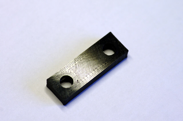
Figure 8. Test Bloick on Kapton Tape
The bed heating time from 17 to 70°C was just over 8 minutes which is fractionally longer that the OEM borosilicate glass.
Everything I’ve read suggests that folk using MIC-6 plate have the surface lightly bead-blasted. I don’t have a bead blaster but I figure I can do just as well with 1200 grit wet and dry emery paper on a large flat block. This will will also reduce those OEM surface grinding patterns. Provided that I just remove the machine marks then I will not have altered the overall flatness of the printing surface (in fact I will probably improve it). Rather than ruin both sides of the plate I left the non-Alcoa side coated in Kapton tape and set about wet sanding the Alcoa Side. The result has a matte look, but at low angles it still produces a reflection. The sanding operation didn’t completely remove the machine marks and there are low points between these that weren’t sanded at all.
With the plate cleaned an refitted I tried another test print. We have adhesion to the plate although there is a partial first layer adhesion issue that I have attributed to the machine pattern low points that weren’t effectively sanded. Part release was fine on cooling. I tried another print with five copies of model distributed in the centre and at the corners of the bed. They all adhered with no lifting issues, but still with minor skipping on the first layer infill. This test proves the flatness of the bed and would be a difficult challenge for a glass bed.
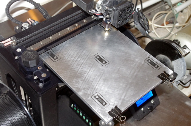
Figure 9. Five Test Blocks on Lightly Sanded MIC-6 Plate
(All with minor first layer infill adhesion issues.)
I
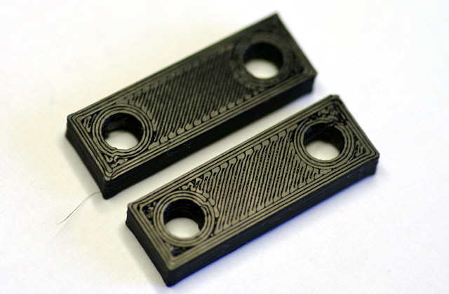
Figure 10. First Layer Infill Adhesion Issues
(Particularly around the holes.)
We’re almost there! I completed a further light sand (as above) followed by a very light chemical etch using Sodium Hydroxide (20 g/litre) by wiping over the surface with a wetted paper towel for about 5 minutes (note that gloves are essential -Sodium Hydroxide will convert tissue into soap). This was followed by a thorough rinse in water. The purpose of the etch is to hit those low spots.
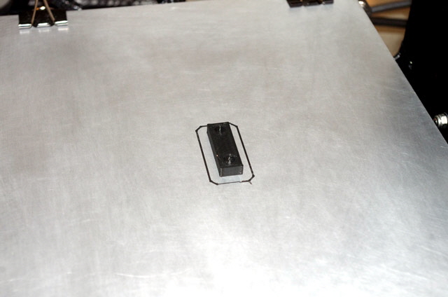
Figure 11. Matte Sanded and Etched MIC-6 Plate
Another test print. and the bed adhesion is perfect with no lifting corners, no first later skipping issues, and ready-release on cooling. The bed side of the print isn’t glossy (as it is with Kapton tape or glass) but it is dead flat. There are unsightly gaps between the first layer filaments which are caused by incorrect Z calibration. This is not really surprising given that I have removed the bed three times for sanding and application of Kapton tape.
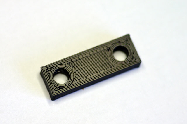
Figure 12. Finished Test Bloc
Dead flat with no First Layer Adhesion or Release Issues
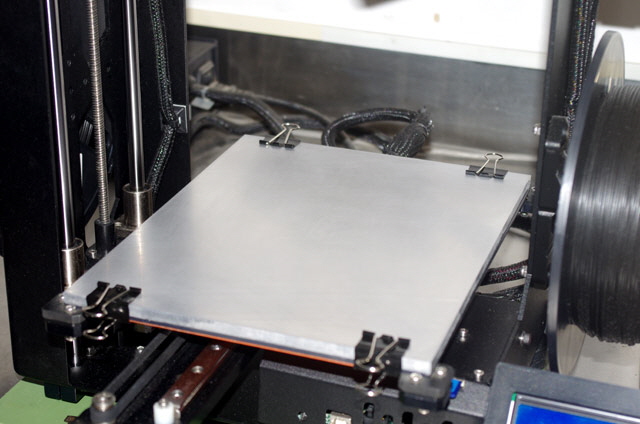
Figure 13. New MIC-6 Heated Bed Platform Complete
(OEM surface grinding pattern all but gone.)
I’ve re-checked the bed level and Z calibration and these are good. So the best method of adjusting the first layer infill is to decrease the first layer hight with a default of 90% for PLA, or increase the extrusion multiplier with a default of 0.9. Both of these are print parameters in Simplify3D.
But I’m good for printing over the whole surface of the bed without lifting issues. And if I really need a glossy print surface then I just need to flip the MIC-6 bed to the Kapton coated side (no leveling or re-calibration required).
Job Done.
|