|
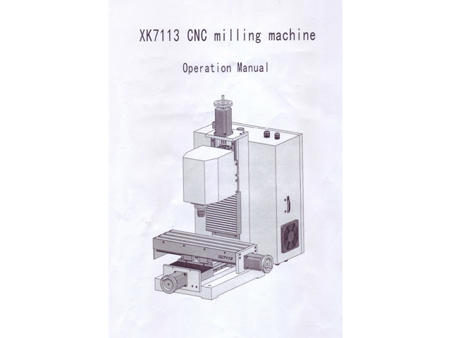
It is time I commented on the XK7113D manual. I suspect that WMT have supplied the incorrect manual because the head stock drawing is not for the XK7113D. It has the wrong physical dimensions (they are too small), it shows a belt drive spindle configuration, a parallel port connector, and the controls have moved on the control cabinet?

Figure 1. Manual Cover Image
The 21 page manual that arrived with the mill is totally inadequate. It is full of warnings and prohibitions that appear to be designed to prevent liability from injury to WMT. It contains very little useful information for use, maintenance or servicing of the XK7113D.
The XK7113D CNC Mill presents a large number of potential hazards (crush, eye, fire, electrical, cut, projectile, …) but these are typical of industrial CNC metal working equipment. This machine isn’t a toy (and even a toy CNC mill can cause mishaps and grief). The user should have sufficient training and experience, or adequate supervision, and take appropriate precautions to prevent harm or damage to themselves, others, property or the machine.
Don’t expect any CNC machine manual to explain how to mill effectively. There are plenty of books and courses on this topic. Even a three year apprenticeship in machining won’t make a craftsman, and for CNC there is more to lean than basic milling including modeling and machine control.
There is a lot of material that, in my opinion, should have been included in the manual. This includes (but is not limited to):
- An index.
- Basic controls and sequencing (Figure 25 et seq. above).
- Basic specifications (these are incomplete, plain wrong or unspecified).
- Mounting drawings (something like Figure 17 above).
- Nomenclature and detailed part descriptions. The three shop drawings have the most basic description of parts (although fasteners have thread specifications and lengths) and the nomenclature isn’t standard.
- Subsidiary manuals for major components (VFD, controller card, stepper motor drive modules, rails and linear bearings, the Z axis brake, …). After a protracted email exchange with WMT I have received a users manual for the VFD.
- Wiring diagram (there is no intellectual property at stake here – the machine is largely built using commercial modules from other manufacturers).
- Basic maintenance including lubrication points, lubricant and frequency.
- Basic fault finding.
- Accessories and upgrades (WMT have missed potential sales opportunities here).
- The manual should be a controlled document with a version and date (and maybe copyright). As a courtesy to WMT I have not posted their manual here, but if you want a copy then please ask contact me. Quite frankly I have found more useful information using on-line searches based on OEM part labels. The only part that I haven’t figured out is the Z axis brake and the associated controller.
The manual presentation and English translation aren’t great, but are infinitely better than if I’d attempted to translate an English manual into Chinese!.
Actually there is probably no need to provide a printed (single sided) manual at all. The user can print this out all by themselves or view a file on the control computer. It could be provided on a cheap USB drive complete with the control card USB driver, Mach3 configuration files and the demonstration software.
Controls
One of the many omissions from the manual is the function and location of the controls on the exterior of the XK7113D CNC mill.
Facing the mill on the left hand side of the control box (Figure 2):
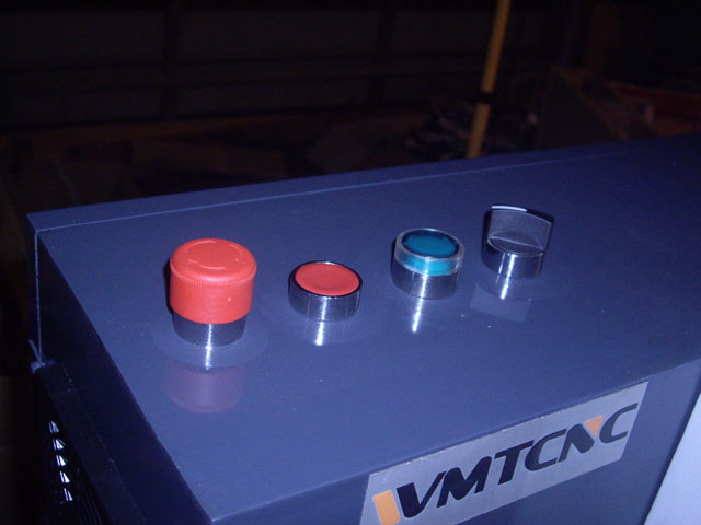
On the top of the control cabinet from left to right (Figure 3):
EMERGENCY STOP. Press down to activate. rotate clockwise to release.
Stop. Press button to shut the machine down gracefully prior to power off.
On. Green push button to turn the machine on. On activation the lamp should liight green, you should hear the variable frequency drive fan and a contactor pulling in.
Stepper Drive Switch. Rotate clockwise to energize the contractor that provides DC power to the stepper motor drive cards.
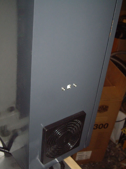
Right hand side of control box (Figure 4):

Figure 2. Main Power Switch

Figure 3. Emergency Stop, Stop, Start and Stepper Motor Drive

Figure 4. USB Port
Click here to link to Mach3.
|