|
I’ve have had a MakerGear LCD controller sitting here for a while and, with the firmware upgraded, the installation should be relatively straight forward following the MakerGear M2 LCD Panel instructions. Note that the LCD controller is stated as compatible with RAMBo Revision 1.2G or later. The RAMBo board Version is printed on the top centre of the RAMBo board. My RAMBo is a Revision 1.3L.

Figure 1. Geeetech LCD Controller
After connecting the LCD controller and powering up the printer the LCD was back-lit but there was no text or graphics - just a Green Screen Of Death (GSOD).
Resetting the printer and the LCD controller did not improve the situation. The LCD controller is reset by inserting a paper clip into the hole on the front immediately to the left of the knob. The second hole further to the left is the piezoelectric sounder. Don’t push anything in here or you risk damaging the sounder. Goodness knows why these aren’t labelled on the case.
The SD Card reader was functional (I could access card files using Protoface from an external computer connected to the USB port (on COM 4).

Figure 2. Green Screen Of Death (GSOD)
Note that the SD card inserts upside-down into a slot on the right hand side of the controller. Like most stuff, if it doesn’t fit then don’t force it. While this is a pretty trivial LCD controller design weakness it could be easily remedied.
There is a screen contrast control accessible through a hole in the centre back of the LCD controller case. Insert a medium sized jewellers Philips screw driver into the hole and feel for the mating wiper on the miniature potentiometer. Then turn it while observing the contrast. All of the graphics display pixels became visible against the back-light, but still no text or graphics. Note that the potentiometer does not have travel end stops. The designers appear to have saved a few cents by using low cost and poor quality pots on the LCD controller. This means that it is possible to set the potentiometers to open circuit! The contrast control is working even though we still have a GSOD.
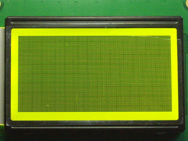
Figure 3. GSOD with Contrast
At this stage it was time to review the wiring and try other LCD compatible firmware. The two ribbon cables were good, as was the RAMBo header board. While reseating the RAMBo header I found it was possible to insert it offset towards the front of the RAMBo by one or more rows of pins. This is another design weakness with the LCD controller. Note that if the wiring had been wrong then the card reader and the LCD back-light would not have worked so these were clearly right first time.
While the header board certainly fits securely to the RAMBo it is totally unnecessary and is a design compromise to make the LCD controller adaptable to a range of printer controllers. An annoying problem with this design is that you are forced to use the card reader on the LCD controller. A good design feature is the use of polarized headers on the RAMBo header board and the LCD controller, but this is compromised by the use of two identical 2 x 5 pin headers. This is a clear recipe for inadvertently swapping the cables.
Next I tried several other RAMBo firmware revisions, all compatible with the LCD controller. Each firmware upgrade was progressively installed and tested through Pronterface. However there was no change in the LCD controller GSOD.
At this stage I contacted MakerGear Support. The only reason that I was prepared to pay $US100 + freight, import fees and tax for this upgrade from MakerGear is on the understanding that if something was dead on arrival, or would not work then I had a direct line for replacement or technical support. After several days and three emails without a response I decided to try and figure out what was going wrong myself.
The first check was a simple Ohm meter continuity and short circuit check of the ribbon cables. They’re good.
Servicing Notes:
For passive components like cables and switches you can happily check conductor continuity and for short circuits between conductors with an Ohm meter and without anti-static precautions with little risk of causing any damage.
Measuring circuit track continuity with an Ohm meter is also unlikely to cause a problem. Either the circuit conducts in which case the voltage drop across the circuit is almost zero and the current from the meter is minimal, or the circuit is open and not subject to current flow. Measuring conductivity between active circuits is somewhat less fault intolerant and subject to error as input protection may cause conduction to the supply rails, semiconductor junctions can turn on, and components can be inadvertently reverse charged.
For active (semiconductor) devices you should apply sensible anti-static precautions. In the olden days MOS inputs were often unprotected and susceptible to static damage that caused all manner of failures including insidious intermittent and long term failures that are inherently difficult to trouble shoot and could occur months after the initiating event. A long time ago when I worked for Control Data Corporation servicing very expensive main frame computers failure to observe the company’s anti-static policies were grounds for dismissal. This took precedence over messing with the bosses daughter! In more recent times most MOS semiconductors have input protection which is very robust. I recall having a DIL MOS quad bilateral switch get stuck in the rubber sole of my shoe and walked it around for a couple of days subject to all manner of physical and static abuse. When I eventually found it and reformed the pins it was completely functional although the case was damaged.
When using an Ohm meter on active circuits polarity and measurement voltage (usually range dependant) can be important. The positive lead of my digital Ohm meters are truly positive when measuring Ohms. The maximum voltage varies from 0.2 Volts to 0.5 Volts depending on the selected range (extending to 1.5 V in diode mode). My analogue meter has the negative electrode truly positive but I still like to use it because the analogue display is somewhat easier to assimilate than a digital display for time-variant measurements such as capacitor charging and discharging (measured using Ohms). In general you want to keep your measurement voltages low and positive with respect to Ground, or negative with respect to supply rails to avoid turning on protection circuitry (unless you are trying to measure that circuitry) or causing reverse bias damage (such as reverse charging tantalum capacitors).
The next mission was to trace out the RAMBo header Printed Circuit Board (PCB) to work out what was being connected from the ICSP 2560 programming, SPI and EXT2 DIL headers on the RAMBo to the two ribbon cables EXP1 and EXP2. The diagram follows. During these tests I found that the header board had a short across the solder mask from pin 6 of the ICSP 2560 programming connector to ground. I cleared this but the pin is designated Ground anyway so the short was of no consequence. Note that the ICSP 2560 header is simply used for additional support for the header board and does not electrically connect to anything.
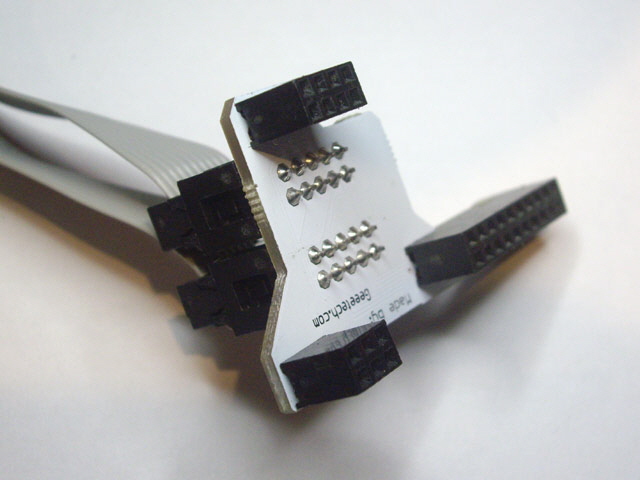
Figure 4. RAMBo Header PCB

Figure 6. Schematic of Geeetech RAMBo Header PCB
The pin outs for the RAMBo EXT2, SPI and ICSP 2560 connectors can be found in the RAMBo manual which also includes a schematic of the whole board. I managed to track down a schematic of the Geeetech LCD controller PCB (you can find it here) which will save some time. I have reproduced a low resolution copy below. Note that the pin numbers for LCD module are not correct on the schematic. Either this is not the current schematic or Geeetech’s documentation is wrong. I suspect the latter.

Figure 7. Geeetech LCD Controller Schematic
I need to remove the LCD controller case. Undo the four corner bolts making sure that you don’t loose any of the nylock nuts which are pressed into the rear of the case. The bolts are a tight fit due to inadequate clearance in the case and printed circuit board mounting holes. They may need to be fully unscrewed clear of the case.
The 3D printed control knob is a forced fit on the rotary encoder shaft and this must be removed in order to gain full access to the LCD electronics. This is another aspect of poor design. The knob should have a grub screw to lock it on to the rotary encoder shaft flat so it can readily be removed for servicing. The only ways to remove the knob without damaging the encoder is either to undo the four case bolts and apply heat to the top of the encoder shaft with a soldering iron (risking damaging the case in the process), or cut through to knob with either a hack saw or a soldering iron (destroying the knob). I used the shaft heating approach.

Figure 8. Rotary Encoder Control Knob
(No grub screw!)
With case open the first thing I noted was the large number of excess solder splashes and solder balls on the Geeetech PCB. This is just tacky construction and should have been cleaned up during manufacture or rejected through quality assurance (but note that there are no quality assurance sticker on the Geeetech PCB).
The two push button switches and the rotary encoder with push button switch can be checked with an Ohm meter. The rotary encoder push button operation was intermittent. I figure that this may be due to damage caused by the original force-fit attachment of the knob (a potential design issue). The rotary encoder will need to be replaced so I desoldered it and removed it from the board.
Referring to the Geeetech schematic (above), the circuit is quite straight forward although some of the nomenclature is weird and the circuit is poorly designed. Neither the switches or the rotary encoder have any hardware debouncing, neither of the two integrated circuits (ICs) have power supply decoupling, and the resistors on the MOSFET gates don’t actually do anything useful.
I already know that the SD card reader is functional so the 74HC4050 Hex Buffer IC (IC1 which acts as a voltage translator to the 3.3 V SD card) and the 3.3 Volt regulator do not require testing. Note that the un-used inputs (three gates) are left floating in the Geeetech design. This is really tacky. Unused inputs can cause oscillation and IC latch-up.
The LCD contrast potentiometer has already been tested as functional (albeit a cheap and nasty component). This simply provides a variable DC voltage to the VO pin on the LCD module. Interestingly this is not filtered.
The EXP1, EXP2 and LCD module header pin connectivity can also be tested with an Ohm meter. It is important to measure continuity from the EXP1 header to the LCD module header, and in particular pin 15 of the LCD header (PSB) which must be connected to Ground. These all checked out as functional. The LCD module pin assignments are not visible (they are beneath the Geeetec board) so here they are for you.

Figure 9. LCD Module Pin Designation (Underside)
(Note that I have desoldered this from the Geeetech board and removed C8.)
There is a 555 timer IC on the board (U1). This acts as an LCD back-light time-out. It is disabled by default by a jumper (SV1) connected to DIR1. The time delay adjustment and back light reset switch are not accessible outside the case. If Geeetech wanted to save a few cents on this design then they could easily do away with this circuitry entirely (8 components and the associated PCB real estate). The timer can be enabled by connecting jumper (SV1) to CNTL. The time delay is controlled by potentiometer (TIME ADJ) on the front of the board. The maximum settable time-out is about 30 seconds which is totally inadequate (another design issue). I can think of several ways that this feature could be improved and made useful.
To test the LCD back-light time-out 5 V DC power must be applied to the LCD controller with jumper (SV1) set to CNTL. I used a bench power supply which also allowed me to measure the LCD controller current at about 73 mA (intuitively about right for the LCD back light). Power was applied between pin 9 (Ground) and pin 10 (5 V) of header EXP1.
Adjusting the TIME ADJ potentiometer will vary the time out and the LCD back light should turn off after less than a minute. Note the potentiometer (without end stops) can be set at open circuit. The LIGHT push button should reactivate the LCD back-light until it times out again. While the circuit design and function are not ideal it does work.
With power applied I also tested the piezoelectric buzzer by applying 5 V to pin 1 of the EXP1 header. The sounder operated just fine.
So, with the exception of the rotary encoder push button everything on the Geeetech board appears to be serviceable. However it is worth commenting on the general layout of several aspects of this board.
The power supply tracks (and tracks in general) are relatively narrow. In general wide short tracks reduce inductance and increase current capacity. The tracks are 0.01” wide with an estimated maximum current capacity of around 500 mA (with an estimated copper weight of 0.5 oz/sq ft).
Routing to pads does not follow best practice to ensure that SMD components will self-centre during reflow soldering (several of the components including IC1, Q1 and Q2 were visibly off pad centres.
track junctions had acute angles (poor layout practice).
the silk screen mask (the writing) on the board was poorly positioned in relation to several components and had only two polarity indicators (at least an additional 3 are required).
The only board information was ‘NADE BY: Geeetech.com’ (yes, ‘Nade’) with no build version or date information or quality assurance marking.
I still haven’t found the fault but we are closing in through a systematic servicing process of elimination. At this stage it appears as though the problem is either in the LCD module (the green board with the display), in the RAMBo, or in the RAMBo driving software.
The next step in this process is to eliminate the RAMBo and the associated firmware. The LCD display is controlled over a serial port with just three controlling signals at TTL (0 to 5 V) logic levels. These signals have different designations depending on where you are looking at them.
|
Serial Function
|
LCD
|
EXP1
|
RAMBo EXT2
|
ATMEGA
|
Arduino
|
|
Chip Select
|
RS Pin 4
|
Pin 4
|
Pin 5
|
PG4
|
70
|
|
Serial Clock
|
EN Pin 6
|
Pin 5
|
Pin 9
|
PJ2
|
72
|
|
Serial Data
|
R/W Pin 5
|
Pin 3
|
Pin 7
|
PG3
|
70
|
|
We can measure these signals with an oscilloscope. While we can also decode the signals to determine the LCD control codes and display data and examine their relative timing this is not necessary. All we need to understand is that Chip Select needs to be at logic 1 (high or 5 V for positive logic) for any data transfer, and the Data logic level is transferred during the logical 0 to 1 transition of the serial clock. This is explained in the ST7920 LCD controller IC data sheet.
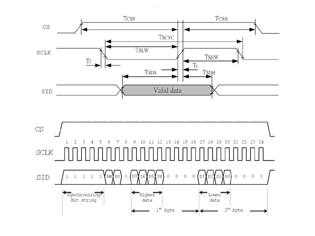
Figure 10. Serial Signals to LCD Controller
I made a simple break out for the EXP1 ribbon cable to attach the oscilloscope and with the LCD controller disconnected turned on the printer and measured the signals.

Figure 11. Chip Select (yellow) and Serial Clock (blue) Signals

Figure 12. Serial Data (yellow) and Serial Clock (blue) Signals
Everything here is looking good. Chip Select is set to logic 1 prior to Serial Clock and Data activity. Data is transitioning between clock pulses and the the clock pulses are regular throughout byte transfers. We can conclude that the RAMBo hardware and firmware are driving the LCD controller. Further, this LCD module has worked for other folk so we can reasonably assume that the signals are not garbage. So the problem appears to be with the LCD controller. We are sending control signals and data from the RAMBo and the LCD controller is not responding.
The next stage is to connect the LCD controller and remeasure the control signals. The problem was immediately apparent. The chip select signal from the RAMBo is being loaded by the LCD controller. It’s logic 1 voltage level has reduced from 5 V to about 0.16 V.
As a further check, with the LCD controller unplugged I measured the resistance on the LCD controller EXP1 header to ground (pin 4 to pin 9). It measured just 40 Ohms (polarity independent). CMOS inputs at DC should be an effective open circuit. So something on the Geeetech board or the LCD module is defective, and the LCD controller is buggered.
There is nothing that I have done in the original connection of the unit or software configuration that could have caused this problem. It is reasonable to conclude that it was dead on arrival.
Let’s see if the problem is repairable. To do this you will need to remove the LCD module from the Geeetech board. This is not a trivial exercise. You must remove every bit of solder from the LCD module header on the LCD module and/or on the Geeetech board. This requires vacuum desoldering equipment. Failure to remove all of the solder risks damage to the printed circuit board tracks on the boards when they are separated. The only alternative is to cut through the header pins between the two boards and desolder each pin individually from each board. In my opinion this is also a design issue. A header plug between the boards would make for easier servicing and assembly.
With the two LCD controller boards separated I measured the resistance between EXP1 pins 4 to 9 on the Geeetech board. The measurement was open circuit so there is no fault here. As an aside this allowed me to inspect the underside of the Geeetech board (otherwise hidden by the LCD module). There is excess of residual flux around the EXP1 and EXP2 header pads and the SV1 jumper pads, all with residual solder. This is further poor construction and finishing.
I completed the same resistance measurement on the LCD module between pins 1 and 4. Just 40 Ohms so the fault is on the LCD module. I inspected the PCB tracks and there are no apparent short circuits. However the RS signal line is decoupled by an SMD ceramic capacitor (C8). Maybe this is the cause? I desoldered the capacitor but the resistance between pins 1 and 4 remained at 40 Ohms. The LCD module is therefore defective and unrepairable.
A good question to be asking is what could have caused this problem? The original installation and this servicing method (complete with anti-static precautions) is unlike to have caused the fault. The LCD module appears to be well constructed (complete with gold plating on the PCB) and has a quality control indicator so I figure this was serviceable when supplied to Geeetech. Given Geeetech’s poor design, poor construction and lack of quality control I figure that they have destroyed the LCD module through poor handling, lack of anti-static precautions, or in their testing processes (assuming that they actually test their product which I have reservations about).
I have passed my findings to MakerGear and they have agreed to replace the defective LCD controller. MakerGear make a quality M2 product so they really should reflect on the quality of their upgrades that they offer from other suppliers. It would seem from the www that a lot of people have had problems with the Geeetech LCD controller and this is potentially damaging to MakerGear’s brand and reputation.
MakerGear have advised that there is an unspecified problem with sending a replacement LCD controller. I have asked them to process a refund but they didn’t take up this offer and a new LCD controller eventually arrived by standard USPS post.
I am so disappointed with the quality of the Geeetech LCD controller that I have decided to design my own specifically for the M2. Let’s do away with the unnecessary stuff entirely. We can use the SD card reader in the M2 electronics case and in the process do away with a ribbon cable and the need for a RAMBo header board. We can turn the LCD back light on or off with a simple switch. I’ll keep the piezo sounder, and obviously we will need to keep the rotary encoder with push button and the LCD display module.
The new board needs to be pin compatible with the existing circuit to maintain the RAMBo firmware compatibility. In order to keep the size and cost down I have specified SMD components and a double sided board.
There is just one tricky aspect to the new design - getting the LCD display and the switches aligned at an appropriate height for a new case. The face of the LCD screen is about 8.6 mm above the face of the LCD board, reducing to 5 mm to clear the edge of the LED back-light on one side. The rotary encoder allows a mounting clearance of between 8 and 13 mm and ideally needs to be near the top of this range. The existing peizoelectric sounder is 9.3 mm high which is compatible with the rotary encoder. However I need to be finding some appropriate profile through-hole mounting miniature push button switches. The best that I have on hand have a clearance of about 7.5 mm from the board surface to the front of the case.
Here is my initial design. Note that this has recently been revised due to changes in the LCD module connector and one connection error in the original.
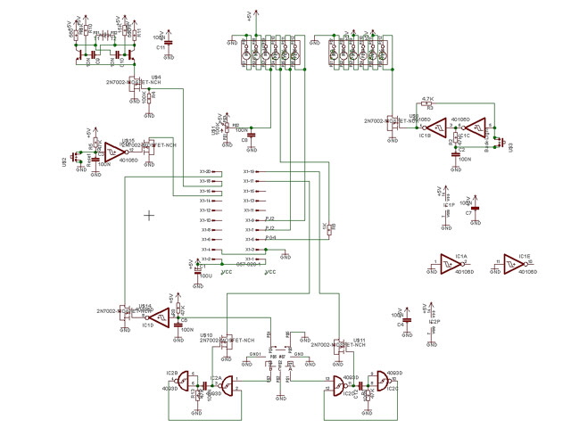
Figure 13. New LCD Board Design (updated 14 May 2017)
All switch contacts (including the rotary encoder) are de-bounced and buffered. The single IC (a Schmitt hex inverter) has power supply decoupling. MOSFET gates are tied ‘loosely’ to ground to prevent inadvertent turn on. The back-light switch is implemented with a push button and a no-race D type flip-flop that is on when power is first applied. The piezo sounder has a discrete 4 KHz multi-vibrator drive to reduce cost and component profile. This design was selected over the ubiquitous LM555 integrated circuit because it is lower cost and offers a differential drive (closer to 10 as opposed to 5 Volts).
In completing the design I found yet another design issue with the Geeetech controller. Current through the rotary encoder is actually very important. Too much or too little and the contact life will be shortened and the switches will not meet bounce and jitter specifications. My design provides optimum current in accordance with manufacturers recommendations to maintain clean contacts.
On Cost
I was amazed to find some identical replacement 128 x 64 LCD modules for just US$5 each! They’re even cheaper for large orders. I have ten on order with white graphics on a blue back-light.
The original rotary encoder is a 15 segment, 30 detent type with push button. I have found a replacement for about $4.00.
I have a large inventory of electronic components and these devices are typically just a few cents each. The most expensive part is a real trim pot with end stops at about $1.50 (compared with a Geeetech pot at 10 c). The tantalum 100 uF capacitor is about 30 c. The Schmitt hex inverter is just a few cents in volume.
The piezoelectric transducer is a challenge at around $5 for a low profile device with integral oscillator. I have knocked this back to about $1 by putting a discrete external oscillator on the board.
The new tactile switches are about 20 c each.
The wiring and headers are a significant cost. I can see why the Geeetech design uses a soldered LCD module (a replacement module is less than the cost of the associated 0.1” header and socket. I’m working on this but for a soldered connection we are talking about 40 c. I have found a Harwin 6 pin SIL bottom entry socket that is reasonably priced and meets profile requirements. We only need two 6 pin connections as opposed to a more expensive 20 pin SIIL board to board connector.
I’ll be getting a board made for this replacement. This will be relatively expensive - perhaps $20 each for limited quantities. For moderate volume production the price per board drops significantly (< $1).
So the total electronic component cost (less cable, plugs, header, case and mounting hardware) for my ten-off design is around $US30. In moderate volume production this drops to less than US$20 per unit. I could squeeze the price down further by using low cost poor quality components and cutting back on a sound design, but there is no point in me replicating Geeetech’s poor design and quality.
Here’s my board design (Revision 2.2). The board is exactly 93 mm wide. As at 9 May 2017 this board is under revision. The new board will be posted shortly.
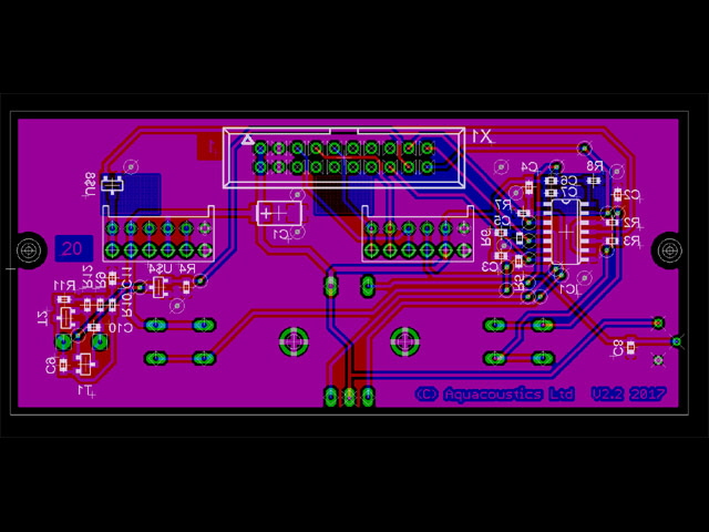
Figure 14. New LCD PCB (Version 2.2 updated 14 May 2017)
(93 mm wide)
I think it is a vast improvement on the Geeetech offering (but then I would). In particular:
All switches and the rotary encoder are hardware de-bounced and buffered.
The single IC and the multi-vibrator are power supply decoupled.
Component profiles fit within a rectangular envelope (for a simple case).
There are no redundant components or surplus gates.
All power supply pins on the RAMBo header EXT2 are utilized.
Track sizes are conservative for current.
There are no acute PCB track angles.
Track connections to pads generally enhance component alignment under reflow soldering.
Components are low cost as opposed to cheap and nasty.
All controls are externally accessible. Only the LCD contrast adjustment is in a recess.
The LCD contrast is side-mounted so you can watch the LCD while adjusting it.
Back lighting is controlled by a push button (on on power on by default).
There is a single ribbon cable that attaches directly to EXT2 on the RAMBo.
A RAMBo header board is not required.
The SD card remains in the electronics case.
The PCB that is about half the size of the original with gold plated pads..
Controls are symmetrically and aesthetically laid out.
Component polarization is identified.
The board has revision information.
The current through the rotary encoder is appropriately rated for maintaining clean contacts.
LCD module case shorting has been eliminated.
The case design is clearly a consideration in the selection of components and particularly their height and their location. With the parts selected the new LCD controller hardware was modelled. This gives precise locations against references from the LCD module (and in particular the display screen, the mounting holes and the 20 pin SIL connection. The model allows confirmation of the board layout for mating compatibility and mounting. The case design can now be completed.

Figure 15. New LCD Controller Model
In designing the case I have found yet another problem with the Geeetech controller! The LCD display is attached to the LCD module by a pressed metal frame with six tabs that pass through the PCB and are twisted to lock the display in place. You can see three of them clearly in Figure 9 above. The tabs protrude below the bottom of the PCB by up to 2.7 mm which is more than the height of the Geeetech 20 pin header (2.54 mm) so the tabs rest on the Geeetech PCB. That’s fine provided the tabs don’t contact anything but on the Geeetech board two of the tabs potentially short signal tracks to ground. They are only insulated by the solder mask and the paint on the metal frame. I have highlighted one of these points of contact using bearing blue on the base of the metal tab (image below).

Figure 16. Potential Short by LCD Tabs
I have revised my PCB design at Figure 14 above to provide clearance for the LCD tabs from any active PCB conductors, components, vias or soldered tabs.
The new 3D printed case has been designed. It is smaller and lighter than the Geeetech case. It also provides more secure mounting for the electronics and ensures that the LCD display is flat and level with the front of the case. This exercise identified another Geeetech design failing. Their case design fails to account for the protrusion of the 20 pin pin connector pins above the plane of the LCD module board so the LCD cannot sit flat in the case.
I still have the bracket to design that attaches the controller to the M2 frame using the two forward electronics case screws. In this position the LCD controller mount is secure, angled for easy use of the controls, is off the bench, and does not interfere with the bed or filament spool for a dual extruder.
I am going to be using brass M3 heat-set brass inserts for the four case screws and also for the control knob grub screw. These are a really handy accessory for 3D printed parts and only cost a few cents each. They provide a much more secure attachment than a threaded plastic part and require no machining at all. They are easily inserted with a soldering iron although they can also be set with adhesive. In the past I have also used embedded nuts to achieve the same end but this requires stopping the print at the appropriate layer and inserting the nuts before continuing the print.
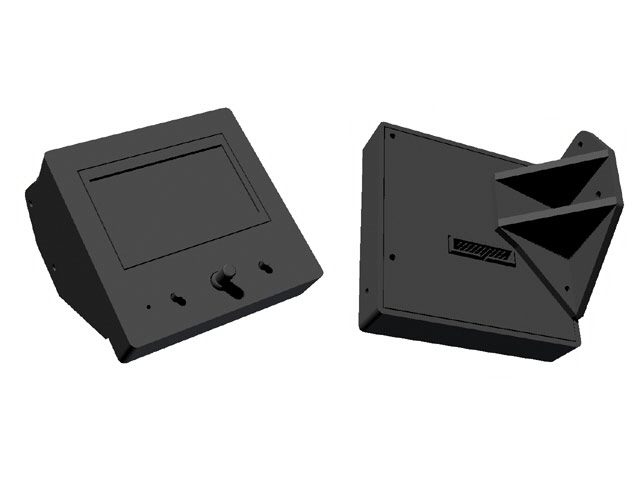
Figure 17. Case and Detachable Frame Bracket Design

Figure 18. Front View of Case and Detachable Frame Bracket Print
(less controller board)
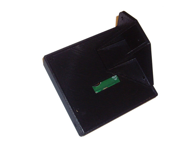
Figure 19. Rear Veiw of Case and Detachable Frame Bracket Print
(assembly less internal controller board)
The printed case is almost a perfect fit for the LCD, perhaps with fractionally too much clearance for the width of the LCD display. The case fits together perfectly and the frame mount is secure and well clear of the dual extruder filament reel and the bench.
Oops, the frame mount holes don’t line up with the M4 holes in the frame, and best I add some text to the two push buttons on the case and the contrast adjustment. I haven’t made any allowance for the thread inserts either. I’ll make these model adjustments and any other necessary tweaks before I post the .STL files.
I’m still waiting for delivery of the boards and the last few components for construction. These should be here within the next two weeks.
I am finally satisfied with my LCD case and bracket. Here is a picture showing these mounted off the electronics case bolts (with the old buggered LCD module fitted for size). Attachment is straight forward although two new long M4 x 12 mm bolts (the existing 8 mm long bolts will only engage one turn which is not adequate). The 0.8 mm deep embossed symbols are highlighted with white typing correction fluid. The LCD controller case has adequate clearance from a dual reel and the bench, does not impede movement of the HBP or inhibit access to the SD card reader. The case is very secure and does not deflect under operation of the push buttons or rotary encoder.
I have just a few more parts and the printed circuit boards still to arrive. I need these to confirm board mounting before I publish the case, bracket and knob .STL files.
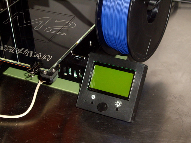
Figure 20. New Case and Bracket
All the parts and the boards have arrived. It takes about an hour to assemble the controller board by hand but, as as this is a new design, it needs full functional testing it before connecting it to the Rambo. Testing took half a day and I found two errors in the board layout. Two tracks were inadvertently terminated on incorrect header pins and were routed on the wrong side of the board (my dumb). The schematic and board layouts in Figures 13 and 14 above have been corrected. The tracks were cut and re-wired with a wiring pen.

Figure 21. Assembled LCD Controller Board (Rear)

Figure 22. Assembled LCD Controller Board (Front)
(Note minor rework above rotary controller U$5)
Here are the test measurements and results:
Vcc and Ground terminate correctly on the LCD module and EXT2.
The controller board (less LCD module) draws 140 uA from a 5 V supply.
The LCD back light switch toggles correctly with power initially applied on board power up. Termination is correct to the LCD module.
The contrast adjustment potentiometer works with correct termination on the LCD module.
The rotary encoder push button works with correct polarity and termination at EXT2
The reset push button works with correct polarity and termination on EXT2.
The rotary encoder operates correctly with correct termination on EXT2.
Two of the LCD control signals have been inadvertently swapped (PJ2 and PG3) and are on the wrong side of the PCB. Corrected with cut tracks and wiring pen. All other LCD module terminations are correct.
The piezoelectric sounder operates at 4.3 kHz with a current of 6.6 mA. Control terminates correctly on EXT2. The pitch might be a little bit high. It is easily lowered by increasing the value of resistors R10 and R12 or capacitors C9 and C10.
With the controller board defects corrected I plugged in the LCD controller module, made up a 450 mm long 20 way ribbon cable, removed the M2 electronics case, and plugged the new controller in to EXT2 in the Rambo (red wire to pin 1 at the front). The new controller worked perfectly first time. I adjusted the LCD contrast potentiometer and set about working through the menus. All good.

Figure 23. Ribbon Cable Seated on Rambo EXT2

Figure 24. Power Applied with LCD Protective Plastic Film in Place
(Note the LCD back light is off for ease of photography.)
The piezoelectric sounder couldn’t be tested with the Rambo but I figure this is entirely due to code as the circuit is fully functional and correctly terminated. I’ll probably need to look through the Rambo code to figure out what error conditions cause the sounder to activate - I expect these to be associated with attempted extrude when not up to temperature.
The electronic assembly fits perfectly in the 3D printed case but before I can install it I used a soldering iron to fit the M3 brass thread inserts in the case bosses and in the rotary controller knob. Four pan headed M3 machine screws (2 x 16 mm and 2 x 20 mm) and an M3 grub screw are required for case assembly. I cut down some 30 mm M3 screws and used the offcuts and a needle file to make the knob grub screw. Fitting the thread inserts is a breeze and they provide a very positive and secure thread with little risk of stripping.
I tried to purchase some thread inserts from McMaster-Carr but they will not export to New Zealand (claiming undue export red tape and cost). I suggest that you use RS Components Part Number 278-534.

Figure 25. Brass M3 Thread Inserts
(RS Electronics Part Number 278-534)

Figure 26. Case M3 Thread Insert Fitted with Soldering Iron

Figure 27. Knob M3 Thread Insert Fitted with Soldering Iron
Assembly instructions are as follows.
- Remove the M2 electronics case lid (three M4 x 8 mm bolts with washers).
- Attach the EXT2 connector with red wire to the front (pin 1). Ensure that the header is fully seated on the EXT2 header.
- Ensure that the SD card and fan are connected. Replace the electronics case lid fitting only the rear M4 x 8 mm bolt and washer.
- Place the LCD controller electronics assembly into the LCD controller case. Fit the bracket to the case back. Fit the case back and bracket onto the case and secure with 2 x M3 20 mm machine screws through the bracket and 2 x M3 16 mm machine screws through the case back.
- Attach the polarized ribbon cable plug at the rear of the case.
- Attach the LCD controller to right hand side of the M2 frame using two M4 x 12 mm bolts with washers through the two front electronics case lid holes.
- On power on if the display appears blank adjust the contrast potentiometer using a jewellers Phillips screwdriver through the hole on the right hand side of the LCD controller.

Figure 28. New LCD Controller Securely Fitted and Operational

Figure 29. New LCD Controller Securely Mounted
Here are the file downloads for the case, knob and bracket (.STL), the LCD controller board schematic and board (Eagle 4.13), and the bill of materials. These files are provided for personal use only and are subject to copy right. If you want to use my design for commercial production then email me.
As at 9 May 2017 I have removed the link to download the LCD Controller Zipped Files.
This is due to a board revision and a few folk copying my design with commercial intent.
I will build you a fully tested LCD controller (complete with case, ribbon cable connector and hardware) using lead-free solder for about US$75 (subject to exchange rate) plus postage and packaging with a no-questions-asked return to base 3 month warranty.
If there is enough interest the price will drop to less US$50.
I also have 8 spare boards (albeit requiring a minor wiring rework) and all components including LCD modules in stock. Please email me if you would like to purchase a board or parts but note that this will require SMD (surface mount Device) soldering and antistatic precautions, and I cannot warrant your work.
9 May 2017. My LCD controller is still working just fine but there is a minor issue with the design that is causing an intermittent (and annoying) problem with the SD card reader. I believe that I have fixed the problem but I can’t be absolutely sure until I have a new printed circuit board made, populated and tested. More to follow on this...
14 May 2017 and the SD card reader issue has been resolved. Here is the story...
Something really weird is happening with my SD Card reader. When I turned on my M2 today the SD card wasn’t detected. After repeated card inserts and M2 power cycles the SD card just wasn’t working. My first thoughts that this could be either dirty contacts on the SD card reader, a poor header connection, or a faulty SD card. These potential causes were quickly checked and eliminated.
Lets try some other M2 configurations and see if the problem still exists.
I removed the LCD controller. Under computer control via USB the original M2 SD card reader is always detected.
Next I tried a GeeeTech (MakerGear) LCD controller (with integral SD card reader). This also always detects the SD card.
Okay. Lets remove the GeeeTech LCD controller and put my own design back in. After refitting the LCD controller the screen was blank. Oops! I had misplaced the header on the RAMBo by 1 Dual In Line (DIL) row towards the front of the RAMBo.
On correcting the header I now had a Blue Screen of Death (BSOD). Bugger! This seems to be the same fault that I experienced with my first GeeeTech controller. Time to investigate further…
Digression to Repair LCD Controller
When the EXT2 header is misplaced by 1 DIL row towards the front of the RAMBo then the 5 Volt supply pins on the RAMBo (pins 1 and 2) are connected to Ground on the LCD controller (pins 3 and 4). The Ground connection on the RAMBo (pins 2 and 3) are connected to the LCD module RS clock line (pin 4). The 5 V supply pins on the LCD controller are not connected to anything.
Note that the GeeeTech LCD controller header can also be misaligned in the same fashion.
With the header misplaced the RS CMOS input on the LCD module is 5 Volts lower than the negative rail (Vss). This significantly exceeds typical absolute maximum CMOS input ratings of Vss - 0.5 V to Vdd + 0.5 V. Under these conditions the input protection diodes (which do a superb job against very high, but very brief, static voltages of > +/- 1,000 V) will exceed their power dissipation limit and fail. It should be noted that MOS gate oxide has a typical breakdown voltage of ~ 80 V, so the problem is not with the MOSFETs, but with the ESD protection diodes.

Figure 30. Typical CMOS Gate Protection Configurations (RCA)
The absolute maximum current through any MOS input should be limited to less than 10 mA. While I don’t have the input protection circuit diagram for the LCD module, even with a 200 Ohms series resistor (which is often incorporated in protection circuitry) a misplaced header will draw more than 20 mA from the RS input. And the result will be a dreaded BSOD.
Double check RAMBo header placement before
applying power to an LCD controller upgrade!
First up I need to replace the LCD module on my LCD controller. This took just 15 minutes (I still have eight spare LCD modules) and, with the header correctly placed on the RAMBo, the controller was working again.
Best I do something about this potential failure mode. A good design will either prevent or protect users from silly mistakes. There is no practical way to incorporate a polarizing pin or shroud on the RAMBo header so I’ll be adding a 1 K Ohm current limiting resistor on pin 5. The maximum current with a misplaced header will be a little over 4 mA worst case.
Now back to the SD card problem…
The SD card problem is only occurring when using the M2 printer with the original M2 SD card reader and my own LCD controller. There is nothing ‘special’ about my LCD controller design. In essence it has the same logical functions as the GeeeTech controller, but with a number of design improvements.
The logic signals to the SD card and the controller come from separate RAMBo processor ports so we shouldn’t expect any interaction between the LCD controller and the SD card reader. What on earth is going on?
Let’s have a look at the SD card reader.
There are a few design differences between the original M2 SD card reader and the GeeeTech design that might be casual.
The original M2 SD card reader design uses simple resistive dividers to convert 5 Volt logic levels from the RAMBo to 3.3 Volt levels for the SD card while the GeeeTech design uses a logic level translator IC. Both arrangements work fine under tested M2 configurations.
The 3.3 V power supply for the SD card on both the original M2 and GeeeTech designs both use three terminal 3.3 V linear regulators, but from different manufacturers and with different specifications. I doubt that this is a problem as both turn on rapidly with stable regulation.
The regulator output filter capacitor on the M2 reader is a 1 uF Tantalum capacitor while the GeeeTech design uses a 0.1 uF ceramic capacitor. I have concerns about both of these values as nether appears appropriate for regulator output stability. Most three terminal regulators specify at least 10 uF low ESR capacitors on the output. However the existing designs are stable.
The M2 SD card also has a power LED driven from the 3.3 Volt supply. This LED is redundant as it can’t be seen with the RAMBo case assembled. I might remove this and save some power some time in the future but for now it isn’t a problem.
Neither SD card reader design establishes true 5 V logic levels on the data output line. They both rely on the fact that 3.3 V is near the minimum logic high threshold for 5 V MOS. While this is not ideal it works. I doubt that the problem lies here.
So the GeeeTech LCD controller and the original M2 SD card reader are not perfect but they both work. I conclude that the problem is not with the SD card reader.
It’s time to change my thinking and look at what the RAMBo sees when looking at the GeeeTech controller and my LCD controller on power up. This is a slightly different perspective than comparing the logic functionality of the GeeeTech LCD controller and my design.
The only apparent difference is the the GeeeTech design does not buffer switch outputs so the RAMBo sees either open circuit or Ground. My controller applies defined logic levels so the RAMBo sees either + 5 V or Ground.
The only switching functions that can change state on power up are the two rotary encoder switches. This was easily tested and sure enough:
the position of the rotary encoder on my LCD controller affects
whether or not the SD card is detected.
I figure that the RAMBo must be doing some other stuff with the associated port other than simply looking at the timing of logic level transitions. Normally on power on the processor ports are tristate inputs until they are defined. The final configuration for the LCD controller inputs must be an input with a pull up resistor, and this should be compatible with standard logic levels. However transitions in configuring the port or defined output at logic level zero may cause port latching when connected to a 5 volt logic high. Note that for many processors output ports will tolerate a short to ground or the rail.
While the problem could be resolved by trolling through the RAMBo software it will be easier to make the rotary encoder open drain (MOS) or open collector (BJT) output. This will also ensure compatibility with future softtware upgrades.
If I’m going to make this change I may as well add an edge level triggered one-shot to provide the rotary encoder with a defined minimum pulse widths, hardware debouncing and anti-jitter. This should also provide improved rotary controller action. While I’m about it I’ll change the other two push button outputs to open drains.
Arguably I could do away with the switch buffers entirely but these provide hardware switch debounce which is sound design practise. Mechanical switch contacts are inherently noisy – they take several milliseconds to change between stable states. During switching they can produce a string of pulses that are relatively slow compared with typical response times of logic circuit families. While it is possible to debounce a switch input entirely in software, a combination of hardware and software is a more robust approach.
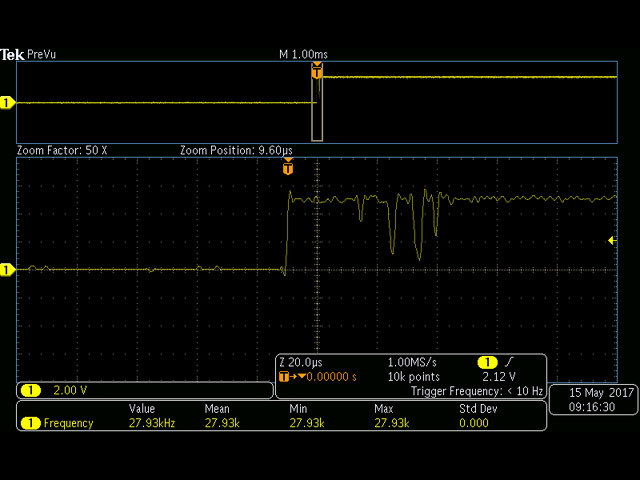
Figure 31. Typical Switch Bounce
(GeeeTech Rotary Encoder with 100 K Ohms in series.)
The new rotary controller circuit has been designed and simulated, and the changes have been incorporated on my LCD board. I may need to tune the two rotary encoder output pulse widths (currently based on 15 cycles per revolution and 1 revolution per second ~ 33 ms per pulse).

Figure 32. Open Drain Non-retriggable One Shot on Rotary Encoder
The new design requires a new LCD controller printed circuit board as there are too many changes to install a patch or just rework a few tracks. It has an additional integrated circuit, some passive components and a few additional MOSFETs but these don’t add appreciably to the cost. The patch at Fifure 22 has also been resolved and the offending tracks have been relocated to the bottom of the board. I have retained the original board dimensions, header placement and switch positions so there is no need to redesign the case.
I’ve updated the schematic and the board diagrams in Figures 13 and 14 above. I will be getting some new boards made in due course.
If you have any questions, comments or suggestions please email me. I reply to all emails. Otherwise click here to navigate to my first ever print and modification, a new M2 fan mount...
|