|
No, I haven’t got time for another ‘repair adventure’, but I recently had cause to play an audio cassette. My ancient Kenwood X-3WX stereo dual deck cassette player refused to work at all on the primary (B) deck (in fact I struggled to even get the tape door to open) and the secondary (A) deck barely transported the tape.
The unit was purchased about 1980 new, but it hasn’t been used at all over the last seven years.
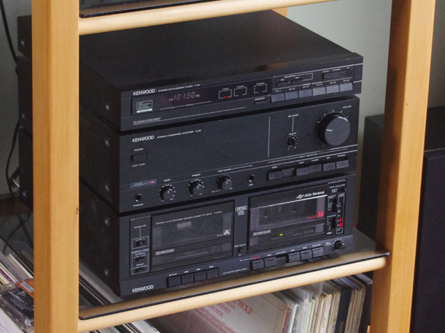
Figure 1. Kenwood Midi M-30 with X-3WX Cassette Deck
(after repair)
If there is an electronics problem then I can probably fix it, but if some significant plastic part is broken then I may not be able to complete the repair (although 3D printers are rapidly approaching a resolution where we will be able to fix almost anything). If there is an irreparable mechanical part then this page will be short.
If the belts on your cassette deck need replacing then with a little care you can do this yourself with minimal disassembly (maybe by just removing a couple of screws to remove the deck from the case and remove the motor platform from the deck to access the belts).
If something more significant needs fixing then, with the right tools, patience and care you can completely dissemble and reassemble your cassette mechanism by yourself, and maybe find and fix any problems, even without a repair manual. But if pulling stuff to bits is not your forte, or you have other pressing things on, then maybe you might want to take your broken deck to a repair specialist along with your credit card.
Interlude
A few years back I went to a local appliance store looking for a replacement element for a toaster. They had a big notice beside their service and parts counter which advised that the cost of spare parts or labour might exceed the cost of a replacement. Sure enough I could buy a new toaster with all sorts of additional functions for less than the cost of a replacement element (which I still had to fit). I bought the replacement element. The repair of this cassette deck is more about love than money, and maybe an element of challenge.
I disconnected the cassette unit from the power, removed the cover and then detached the primary and slave decks from the chassis, taking care to photograph every screw and connector to aid with re-assembly.
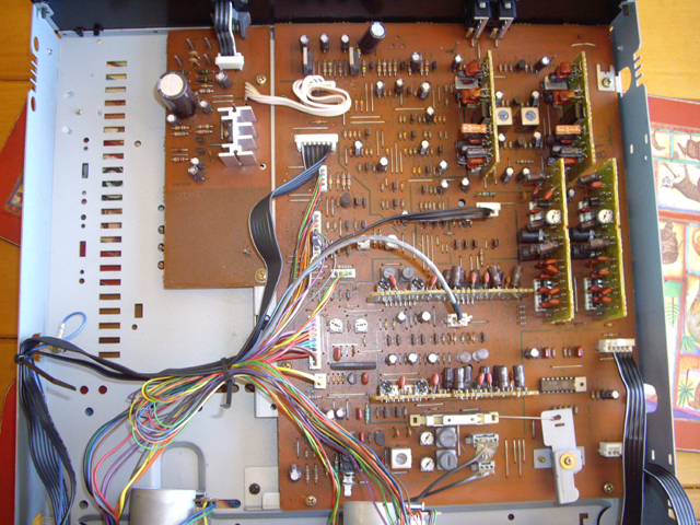
Figure 2. Case Cover Off - Printed Circuit Board
The first things noted were broken belts, a desiccated spider and its web, and a bit of dust. The primary rubber drive belts on the main deck had turned to a sticky black goo adhering to the associated pulleys. The other belts were distorted, cracked and had stretched or broken.
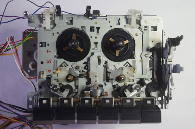
Figure 3. Primary (B) Deck Mechanism
Before doing anything else I set about measuring the belt sections and goo as best I could using veneer callipers. The majority of the belts were approximately 1 mm square section, but one was about 1.2 mm square section and the goo was formerly one (or two) flat belts approximately 5 mm wide and 0.6 mm thick.
I set about meticulously cleaning the black goo from primary drive pulleys and drive path with cotton buds and mineral turpentine, followed by cotton buds soaked in hexane, followed by even more cotton buds and isopropyl alcohol.
Next I inspected the capstans, rubber pinch rollers and the heads. These seemed to be in good order with no problems immediately apparent (but the rollers might have gone hard over time). This was followed by inspection of the decks looking for obvious problems like cracked plastic components, stripped gears or missing springs. Everything, other than the belts looked fine.
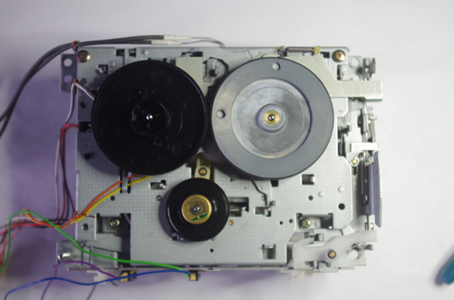
Figure 4. Slave (A) Deck Mechanism
Okay, the belts are all stuffed and I’ll need some new ones. There are a number of websites that sell cassette belts. The problem is that I don’t have the originals to measure the belt length (remember that they had turned to goo or had permanently stretched, cracked and broken). I can’t find a standard belt replacement set for my Kenwood, and I don’t have a service manual or a spare parts list.
I used a piece of fine sewing thread with a slip knot to form a tight belt loop over the assembled pulleys, cut the thread loop and measured its length. I repeated this twice for each belt. The measurements were confirmed within a couple of millimetres. Most cassette drive belts have between 5 and 10% stretch (sometimes extending to 15%). Thinner section belts will allow somewhat more stretch than a thick belt. With my thread length measurements and the cross sections that I had measured earlier I selected the nearest standard belt length that would give about 7% stretch.
The replacement belts arrived in about a week and were only a few dollars each. I fitted the new belts and reconnected the tape mechanisms to the circuit board. With any luck the decks might roar into life.
When doing this sort of test you will need a test tape. Most decks have switch mechanisms that sense when a cassette is inserted, whether it is recordable, and sometimes the tape type (ferric or chromium oxide). Don’t use you favourite cassette or a collectors item worth more than the deck you are trying to repair. Chances are the tape will spew into the mechanism or be stretched, graunched, or somehow chewed up. I can think of a few ‘artists’ that made tapes just fine for testing.
Bugger! Neither deck would not retain play drive although both worked fine for fast forward and reverse and the motors were turning. Noting the motor direction at this stage is a good idea.
Cassette mechanisms are (by definition) primarily mechanical due to their vintage although you can expect to find a micro-switch or two or perhaps an optical detector. This is good because with enough thought, careful observation, and delicate hand manipulation, you can work out what should be happening in slow time and you can usually see a problem directly.
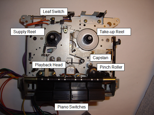
Figure 5. Some Basic Part Nomenclature
Both decks on this unit operate from piano switches extending through the front panel. If these are used to select an operating mode, and the tape transport is inspected to determine what direction stuff should spin in, then you can gently turn the fly wheel (usually a die-cast solid wheel early in the drive chain) by finger and see stuff operating. Don’t force the flywheel. If it is stuck or resistive then something isn’t working and you will need to investigate further. Depending on the gearing, the fly wheel may need to turn several times to activate a particular operating mode. Unless your deck is direct drive and reversing (most aren’t) then the motor will almost always turn in only one direction.
In play mode you’re looking to see that the pinch roller engages with the capstan, that the capstan is rotating, that the playback head is in contact with the tape, and that the take-up tape drive is being driven - all with minimal friction or noise. If these things aren’t happening then you will have no tape drive, no tape take-up (this will cause the tape to spew into the transport mechanism), and/or no audio.
In forward or reverse the drive should be direct to one of the reels and somewhat faster than play.
To activate record mode there will usually be a mechanical lever at the top of the tape that must be pressed upward by the write-protect tab on your tape case.
With nothing obviously broken externally it was time to delve into the guts for explorative surgery.
Cassette mechanisms are one of the most complex, intricate, precise, and in some ways delicate, electro-mechanical devices that you are ever likely to come across. It is therefore imperative that you proceed with disassembly in a logical manner using care, patience, a means to record every step of the process (aren’t digital cameras great), and laying out parts in a logical fashion. It is appropriate that I issue a rather long list of cautionary notes:
- Don’t force anything anywhere – it will probably break.
- Plastic parts may have become brittle with age so handle these with care.
- Head alignment and tape speed are actually really important to audio quality. You don’t want to be messing with any head alignment screws unless you have the equipment and test tape for readjustment. Chances are that you may need to adjust the motor speed after any belt replacement and realign the heads after disassembly. To do this properly you will need a test tape and an oscilloscope.
- Think and take photos before you remove any part, screw or circlip. You don’t want to end up with a pile of levers, gears and springs that you can’t reassemble.
- Think again before you remove screws coated in coloured lock-tight (usually red or green) – they are likely to be critical alignment fasteners and they may have critical torque settings. Maybe you can remove this bit as a subassembly?
- Use the right tool (and a tool in good order) for removing stuff. A full set of jeweller’s screw drivers will set you back just a few dollars.
- Try and anticipate where the bit you are removing might fall or fly. If you are removing (or reattaching) a spring or circlip then it is likely to ping off into the place where lost socks go, or head straight for your eyes. Keep a hold of it and try and limit where it might land (this is one reason why technicians wear safety glasses and white lab coats with pocket flaps). A clean workspace may help you find an errant part.
- Avoid damaging other stuff with your screwdriver. Scratches on the case exterior in particular are not good form.
- If you love your spouse then for goodness sake put an old sheet on the dining table before you use it as your repair centre and ensure the table is not booked for a dinner party some time in the next few weeks.
- The drive mechanisms and gears can be very fine so don’t go forcing levers or spinning gears or pulleys at random with any force to check stuff out - you might end up causing irreparable damage. (Didn’t I say this already?)
- Don’t lubricate everything with CRC or grease and don’t clean stuff with a solvent that will soften or dissolve the plastic parts. Too much lubricant, or the wrong lubricant or solvent, or the right lubricant in the wrong place will stuff your deck and might damage your tapes.
- Be on the lookout for transparent Mylar washers and anything that might contain ball-bearings. The former are almost impossible to see and therefore easily lost (or never found in the first place); the latter will suddenly appear on your bench leaving you with the problem of working out where they came from.
- Avoid causing damage to wiring and protruding parts through handling. If necessary fit some protective rods or other hardware to the chassis to prevent damage to delicate parts. These fixtures can also stabilize the deck that you are working on.
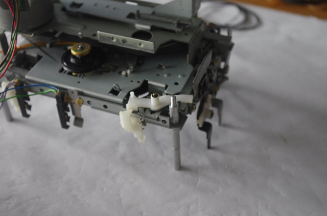
Figure 6. Support Rod to Protect Reverse Lever and Leaf Switches
- When sticking stuff back together make sure that any wiring is not pinched between parts or flopping around next to rotating pulleys, belts or levers. The wires will be attracted to the point of potential damage by an unexplained force called providence.
- Electrical signal sockets should be removed and replaced without pulling on the wires and without force. Look to see if there are any retention catches on the socket. When re-making the connections double check that you have the correct cable and polarity, make sure the connection is seated firmly, and have a quick visual check that there are no shorts between the wires above the plug (particularly on the audio connectors).
- Check that the screws you are about to replace are the correct size and length (which is why you need to keep them in a logical reassembly order and take lots of photos). When inserting screws they should normally be perpendicular to the surface of the part. Turn them gently anti-clockwise (backwards) and feel for a gentle ‘clunk’ which identifies the start of the thread. If you don’t do this, particularly with screws that self-tap into plastic bosses, you will end up stripping the boss. When a part is held in place with a number of screws, fit them all to within say one turn of flush to aid in alignment of the part, and then go around and gently tighten them. If the screw is too long or is difficult to turn then take it out and find the correct screw before you break something.
- Disconnect the power supply. If you get electrocuted then you won’t be able to finish the repair and listen to your favourite tape.
Interlude
Quite some time back I worked as a computer engineer. In the early days of computers there was usually a lot of electromechanical stuff (relays, motors, tape drives, …) and programs and data were often stored on punched cards.

Figure 7. Fortran Punch Card
(unused – no rectangular punched holes in the array)
The data was read by passing the cards through an opto/mechanical or electromechanical reader which detected the presence or absence of physical holes punched in a numerical array on each card. Even a relatively simple program might be stored on a stack of several hundred cards. The card readers transported the cards at quite high velocities through stainless steel guides to reduce data read time. While servicing one such unit I managed to inadvertently misalign two of the stainless steel guide plates by somewhat less than 0.002” (0.05 mm). The test deck of 1,000 cards fed into the machine at the speed of light but nothing came out on the collection platen! I didn’t even have time to stop the reader off before the entire test deck had disappeared. It took almost an entire day for me to clean the confetti out of the drive. The point of this story is that sometimes precision mechanical alignment is very important in material transports, and getting it wrong might instantly fill the mechanism with destroyed media – both being directly applicable to cassette mechanisms.
I started disassembly with the simpler slave (A) drive. About half way through disassembly I found a torsion spring that had lost its torsion post. I had to complete the disassembly to find the tiny piece of plastic that had broken off. There were also two cracked plastic components but everything else seemed in good order. I set about carefully putting the deck back together, drilling a small hole in the chassis and bending the end of the torsion spring to fit the improvised anchor point.
Note on Removing and replacing Circlips
There are numerous small circlips in these Kenwood cassette decks. They are used to retain levers, gears and pulleys in their right place on a stub shaft or axle. Most are simply split flat plastic washers but some are of the conventional three-tab metal variety.
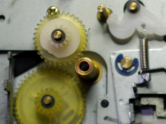
Figure 8. Tiny Circlips Galore!
(The black split washers on the gear shafts are just 3 mm in diameter.)
The plastic ones are readily removed by sliding the tip of a needle under the circlip and gently prying upward against the retained part. They are replaced by simply aligning them with the top of the shaft and gently pressing down on opposing sides with a pair of tweezers.
The metal circlips are slightly more challenging to remove. Preferably place a fine flat screwdriver into one of the gaps between the circlip tabs and the shaft and gently pry outwards against the shaft. To replace the circlip, align the opening with the groove in the shaft. Then use a fine pair of pliers between the shaft and the middle of the circlip perimeter to press the circlip home. If you try and push circlips off and on with a screw driver there is considerable risk of scratching something, stabbing yourself, or having the circlip ping off into the ether.
With reassembly complete I connected the slave deck to the motor drive and audio and turned the power on. The drive was operating beautifully (except the motor would not turn off). There was no mechanical noise at all and all functions were operating correctly. When I inserted a tape the audio sounded great with no ‘wow or flutter’ evident.
With the power disconnected I checked the function of the electrical leaf springs with a multimeter. Some of them were making no electrical contact although they appeared to be physically closed, and one was permanently closed. I cleaned all of the leaf switch contacts on both decks using 1200 grit carborundum paper (but a points file or nail file would have done the job).
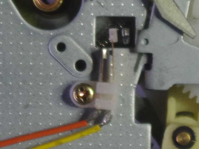
Figure 9. One of many Tiny Leaf Switches
The continuous motor drive was due to the permanently closed leaf switch caused by those two cracked plastic components. I was tempted to repair the broken plastic and realign the switch with the driving solenoid, but I figured that the switch was securely mounted where it was. I gently bent one of the leaf spring contacts open. The slave drive is pretty much good to go.
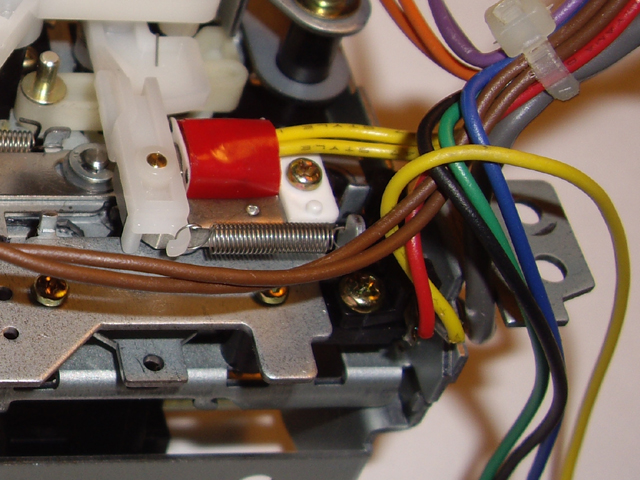
Figure 10. Closed Leaf Switch under Twin Yellow Cables
(Can you see the cracked plastic parts immediately below the bottom right hand machine screw?)
The primary drive with auto reverse, record, and high speed dubbing has a much more complicated mechanism than the slave. I progressively pulled the deck to pieces.
Straight up I could see that there was a missing tension spring on a reversing lever. The lever was flopping about on its guide pins and there was a notched metal post and an aligned hole where I figured a spring should have been. The spring had gone. It was not lodged in the mechanism, or on (or under) the circuit boards. I declared it lost in action sometime over the past 10 years. I found a likely replacement in my ‘spare springs’ jar.
Interlude
From time to time you will end up with mechanical stuff that is totally beyond repair. Rather than throw it back in the dumpster from which it probably came (or put it out for recycling) I like to recover the screws, nuts bolts, washers, gears, shafts, magnets, springs, and some of the serviceable electrical components. These end up in my spare parts collection. The remaining stuff then goes to the recyclers.
The belts that had turned to black goo had been transported through the mechanism so each part had to be cleaned and inspected. With most of the 143 parts removed and nicely laid out I had only found two broken bits on the supply tape reel, neither of which should be causing a tape transport problem There were no other obvious faults or spare bits floating in the mechanism.
The jammed cassette door had fixed itself when the deck was removed. Either the release catch had been stuck or the door had become miss-aligned. I removed, cleaned and refitted the damping gear and inspected the door spring just in case there was a problem here. I love these doors when they are working. They latch securely and open smoothly under the action of the damper.
During disassembly a tiny ball bearing appeared from somewhere. It was going to take some thought to work out where this had come from. A useful technique is to look for cyclic wear marks on metal surfaces that don’t align with other parts. Also think about where a single ball bearing might reasonably be used.
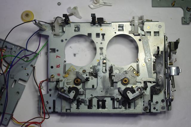
Figure 11. Deep in the Guts with an almost bare Chassis
Maybe the belt goo was the only problem? I set about reassembling the drive, locating the ball bearing’s home in the process, checking that all the levers and gears interacted smoothly without undue force, and applying a small quantity of molybdenum grease from a syringe in the places where it had been originally (mainly around the piano switch slide plates and cam drives).
During reassembly I found a more logical order for putting some stuff back together (and as it transpired also for pulling stuff to bits again).
Turning the flywheel by hand and working through the modes there was something still amiss with the end of tape sensing. In play modes the heads would lift to the tape and then suddenly disengage. If I pressed gently on the cracked tape take-up spindle the deck would stay in play in one direction. The auto reverse was also playing up. Sometimes it worked and sometimes it didn’t.
Time to pull the deck down again. The second disassembly only took a couple of hours. I found that I had managed to misalign a lever associated with the auto reverse during the previous re-assembly (or had it dislodged during testing). I also managed to break two of the leaf spring electrical wires during handling. I left these disconnected for now. I was going to have to think hard about how the end of tape and auto reverse functions worked.
End of tape is sensed through friction clutches on the underside of the tape reels. The supply reel clutch was not working. Those cracked plastic bits were the cause. I repaired the plastic using super glue, carefully scraping off any excess.
I set about rebuilding the end-of-tape mechanism, testing the functionality as I went. A simplified sketch of the mechanism is essential to understand how it is supposed to work.
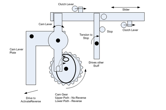
Figure 12. Simplified Diagram of End of Tape Auto Reverse Mechanism
The tape reel friction clutches move tiny levers that drive a plastic slider to the right in the diagram. The active forward or reverse reel provides the drive, but only when the tape is not at the end. These were working just fine. There was no apparent tensioning mechanism for the slider which seemed odd. On review of my disassembly photos I found that I had misaligned the plastic tensioning lever in the previous reassembly (oops – but nothing broken). This only partially tensions the slider due to a stop.
There was nothing obviously wrong here so I switched my attention to the cam driven lever at the left hand end of the slider. If I pressed gently on the lever towards the slider then the auto reverse function would not actuate (the normal play condition). When I took pressure off the lever the pivoting cam lever plate rotated clockwise and auto reverse mechanism actuated (this was happening all of the time and it shouldn’t, except at the end of tape).
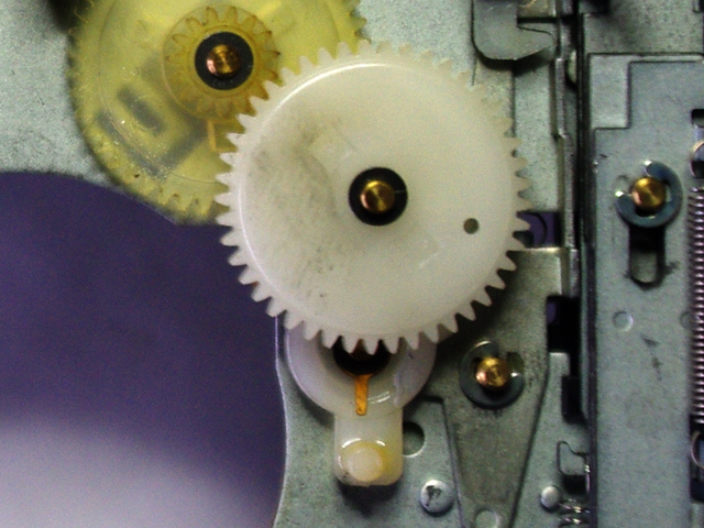
Figure 13. Cam Gear, Cam Lever and Pivot Plate
(If you look carefully you can see that the copper flat tension spring on the cam lever is off centre. I also have some more cleaning to do.)
I feel like I’m getting somewhere at last. The slider is driving the cam lever, the cam lever plate is actuating the auto reverse, but the cam lever isn’t following the correct path in the cam unless I press gently on it. There must be something wrong with the cam lever.
On careful inspection the cam lever flat tensioning spring was off centre. I hadn’t previously disassembled the cam lever so this fault was not of my making. I removed the cam lever and set it back on centre. The end-of-tape sensing and auto reverse actuation now functioned correctly. Whoot! (an expression of joy).
Half way through reassembly a tiny circlip took off somewhere. Darn! I went over every inch of the work bench, the floor, stripped (not particularly attractive) and shook down my clothing, including shoes and socks. No circlip! I got dressed and set about dissembling the deck for the third time just in case the circlip had lodged in the mechanism. No – it had disappeared. I improvised a spare by cutting and filing an appropriately sized stainless steel flat washer and set about reassembling the deck for the third time!
With everything back together and the two broken wires soldered back in place, the service manual that I had ordered on eBay arrived. Excellent! Although there are no specific instructions for disassembling the deck mechanisms there are exploded parts diagrams for each drive. This allowed me to confirm the location of the missing spring and the wayward ball bearing on the primary drive. As it happens I had got these right. Interestingly, the end of tape cam lever detail was slightly different than the one installed in my deck. Perhaps this was a modification caused by a performance issue?
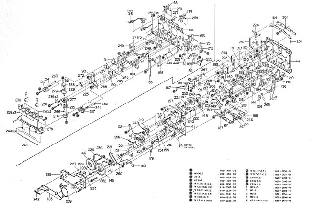
Figure 14. Primary (B) Deck Exploded Parts Diagram
(Kenwood Corporation (c) 1986-8 Japan)
The manual identified that I had got the main drive belt configuration wrong on the primary deck. What I had implemented using two belts worked with everything spinning in the right direction but it wasn’t as designed. This is a consequence of the main belt turning to goo and my incorrect assessment of the drive path based on functional requirements.
I set about measuring the correct drive path length for a new belt. To complete my tests I installed a temporary flat rubber band. Note that rubber bands have too much stretch and insufficient working life to be a permanent fix. They also tend to wander off centre on a flat drive and then jamb stuff – fine if you are operating the deck by finger but potentially catastrophic if you are driving the deck with the motor.
With the rubber band in place I set about working through the modes again by hand turning the flywheel. Everything was working correctly now with no odd noises, or force on the drive. The deck will work again! I just need that new belt to arrive so I can get on and adjust the motor speeds and head alignment.
The replacement belt arrived, was duly fitted, and the decks were reassembled into the case and connected. Both decks are now fully functional with no discernable audio wow, flutter or frequency change, and no drive noise. In fact the units sound so good I’m not even going to bother checking the tape speed or head alignment.
Job well done!
For the record the replacement belts that I have fitted to my Kenwood X-3WX are the following part numbers from Turntable Needles http://www.turntableneedles.com/. I’m not saying that these are perfect replacements (or providing any warranty statement of fitness for purpose) but they fit and work on my decks.
|
Slave Deck
|
Kenwood X-3WX Cassette Mechanism Ass’y (A) (D40-0357-05)
|
|
Turntableneedles Part No.
|
Ref.
|
Part No.
|
Description
|
Comment
|
|
SBO4.0 Square Belt, Orbicular 4.0 Inch
|
55
|
D16-0121-08
|
BELT (AUTO)
|
Flywheel to Auto Pulley
|
|
SBS6.2 Square Belt, Small 6.2 Inch
|
54
|
D16-0120-08
|
BELT (FR)
|
Flywheel to Clutch Lever Pulley
|
|
SBO7.0 Square Belt, Orbicular 7.0 Inch
|
53
|
D16-0119-08
|
BELT (MAIN)
|
Motor to Flywheel
|
|
|
Primary Deck
|
Kenwood X-3WX Cassette Mechanism Ass’y (B) (D40-0323-05)
|
|
Turntableneedles Part No.
|
Ref.
|
Part No.
|
Description
|
Comment
|
|
SBO5.4 Square Belt, Orbicular 5.4 Inch
|
221
|
D16-0118-08
|
BELT (FRB)
|
Motor to Forward/Reverse Pulley
|
|
SBO5.7 Square Belt, Orbicular 5.7 Inch
|
316
|
D16-0221-04
|
BELT
|
Take-up Reel to Tape Counter
|
|
FBM10.2 Flat Belt, Medium 10.2 Inch
|
220
|
D6-0117-08
|
BELT (MAIN)
|
Motor to Forward and Reverse Flywheels
|
|
Corollary - Amplifier Balance Control
During my testing on this repair I identified that the balance control of the main amplifier has ‘gone intermittent’. Balance control is usually implemented with a potentiometer (variable resistor) that has a moving contact that slides over a fixed resistive film. While potentiometers are notoriously noisy at the best of times, if they are not used occasionally then dust and other contaminants can build up on the resistive film, insulating it from the wiper contact.
This is one of the few repair jobs that I recommend using CRC, WD40, or a proprietary electrical contact cleaner for. The trick is to inject just a drop or two onto the resistive film and then exercise the control for a while. Don’t go spraying everything in sight with lubricant from the can. Firstly WD40 smells, and secondly it has a solvent base that might dissolve some other component or damage the case.
The purpose of this exercise is to just to clean the contact areas of the resistive film and the wiper in the potentiometer. The lubricant simply loosens up the surface contamination and dust. Exercising the wiper moves the contamination off the contact area between the wiper and the resistive film. The lubricant should eventually vaporize.
Okay, the balance control is now working reliably (although I will probably never use it again).
While the cover is off and the amp is disconnected from the power I gave it a good clean with a vacuum cleaner and a soft nylon paint brush. Dust on the heat sinks and vents can impede cooling – it can also result in tracking issues on printed circuit boards and connector problems. I recommended that you don’t use compressed air because it will blow dust all over the place and force debris into places that you didn’t intend. While you’re gently cleaning the components don’t be tempted to try and realign them vertical like a row of soldiers. Sure they look ugly on a crazy angle but they work right where they are, you will probably never have to look at them again, and they don’t need fixing yet.
|