|
This page describes my continued experiments with lost PLA casting. I have modified my initial green sand only process to incorporate investment.
I’m wanting to make a replacement catch for a friend’s bread maker. Let’s call it a raisin catch because at a designated time/temperature it releases and dumps raisins into the dough. The original catch was molded high temperature plastic and was broken due to undue force trying to clear a jamb. The part is quite small at just under 30 mm long with a lot of important dimensions. Bread bakes at about 200°C so I figure that it must be a high temperature plastic. The part can’t be repaired with adhesive, plastic or solvent welding as it isn’t strong enough at elevated temperatures, and welding is likely to alter critical dimensions.
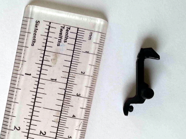
Figure 1. OEM Part
While I can 3D print a replacement part most 3D printing resins are relatively low temperature plastics that won’t be functional at this temperature. So either I can machine a replacement from a high temperature plastic or try and cast one from aluminium.
This is a great project to revisit my PLA investment casting process. Machining the part would be rather complicated, requiring very precise milling on three orthogonal axes, but I may come back to this.
I started by drawing up the part and making a model. This was scaled by 1.5% to allow for aluminium shrinkage and printed. The OEM design was modified slightly to improve the print but the functional dimensions have been preserved. I have a low temperature functional catch.
Now I need some investment plaster. Let’s try plaster of Paris. The raisin catch was adhered to a piece of Perspex sheet and a small plastic jar was glued to the base sheet to make a form.
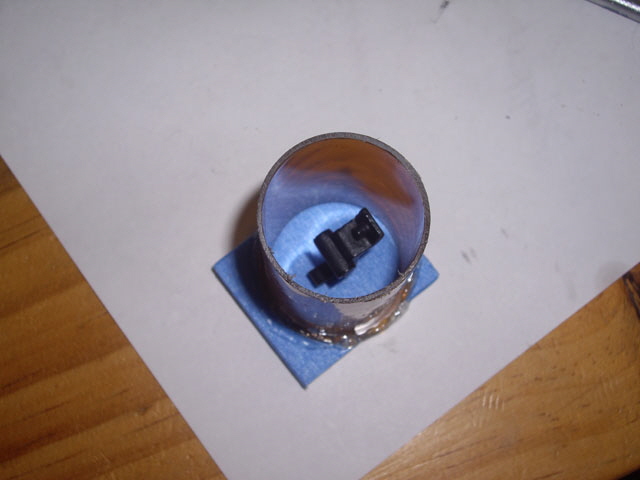
Figure 2. Mounted and Ready for Plaster of Paris Investment
The plaster of Paris was mixed with water and poured into the form and I left this for several months to dry (it didn’t need this long but I got distracted by other stuff).
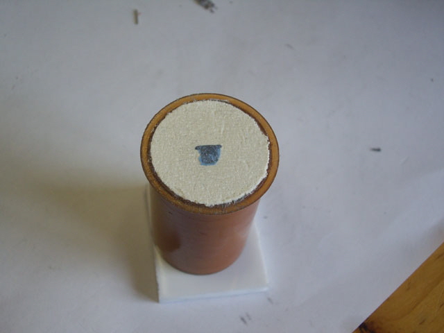
Figure 3. Investment Poured and Air Dried
Melt out time. I placed the plaster mold upside down over a tray and heated it up to 231°C for about an hour. Most of the plastic melted and flowed from the mold, leaving a film on the mold cavity and a drip at the lower edge. After cooling we’re good so far – the mold hasn’t cracked. The reason for this step is to minimize ash being left in the mold after the subsequent burn out.
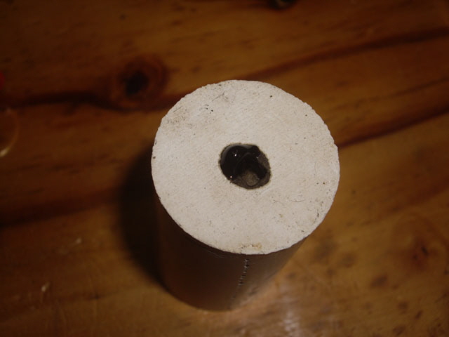
Figure 4. Mold after PLA Melt-Out
Now for some serious heating to burn out the PLA remnants. I put the mold in my gas furnace inside a steel crucible to prevent direct flame impingement and heated up to red heat over 20 minutes and then let it slowly cool. Darn. The plaster has shrunk and severely cracked. The good news is that there was no plastic or ash at all in the cavity, and the cavity detail has been preserved. There was one moderate air bubble visible in the mold. But the cracks and loss of dimensional stability means that plaster of Paris won’t do the job.
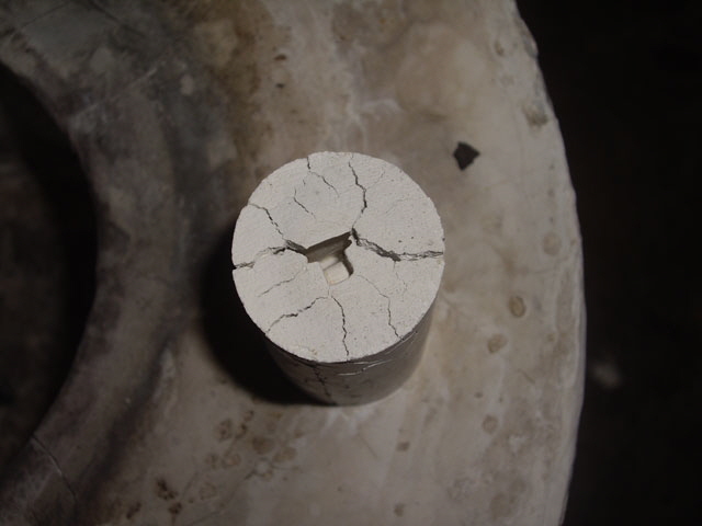
Figure 5. Severely Cracked Mold after Burn Out
(Crashed and burned!)
Commercial investment mixtures seem to be closely guarded secrets, however some research suggests that simply mixing plaster and sand will prevent cracking and shrinkage. The mixing ratios seem to vary from 1:1:1 to 2:4:1 of plaster of Paris : sand : water by volume. Let’s try 1:1:1. I’m going to use my molding sand which also has some clay and refractory in it.
I mixed up the slurry and poured a small puck about 50 mm in diameter and 10 mm thick onto a plastic sheet. It was slightly pink due to the clay content. After an hour to set I removed it from the sheet. The contact surface is dead flat and smooth so it should make for a good impression of the plastic part. Then I baked it in an oven at 110°C for an hour. The pinkish colour has changed to off white and no cracking so far.
Now into a steel crucible and back into the furnace at ~700°C for 15 minutes. The mold was starting to glow orange so had there been any PLA it would have truly vaporized or burnt to ash. I dropped some small pieces of PLA into the crucible and they disappeared within seconds leaving no residue.
On cooling the puck is a brittle refractory with no cracks at all. The surface can be scratched or chiseled with light pressure as you might expect from plaster of Paris. The base of the puck is still dead flat and the pour pattern on the top has retained its detail. The puck has retained its dimensional stability. I cracked it in half in a vice. It was brittle but otherwise quite robust. There are no air bubbles visible in the section (but this was probably more good luck than good management). The investment is also relatively porous which is good (I can suck air through the 10 mm thickness). I figure, on the basis of the relatively fast burn-out that it will also withstand thermal shock.
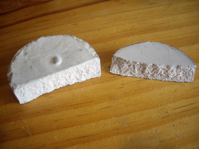
Figure 6. Sand and Plaster of Paris after Burn Out
Okay. The 1:1:1 mix looks like it’s going to be good as investment.
The last thing I need to sort out is getting rid of air bubbles when pouring the mold. As it happens I have a couple of vacuum pumps. Let’s see if I can get these to work satisfactorily. I mixed up some more investment and put it in a small jar under an improvised bell jar.
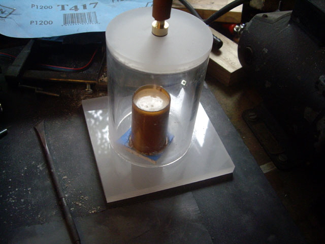
Figure 7. Vacuum Degassing with Investment about to Spill from Form
On starting the pump the investment mix bubbled out of the container. Surely there wasn’t that much air in the mix? And the mix started to set to a gel state really fast. Maybe the vacuum is too severe, casing the water to boil? A quick test was to try the same experiment with just water in the beaker. Sure enough the water is boiling within a few seconds. So vacuum degassing won’t work for a water-based investment. It introduces more bubbles than it removes and rapidly depletes the water required for hydration of the plaster of Paris.
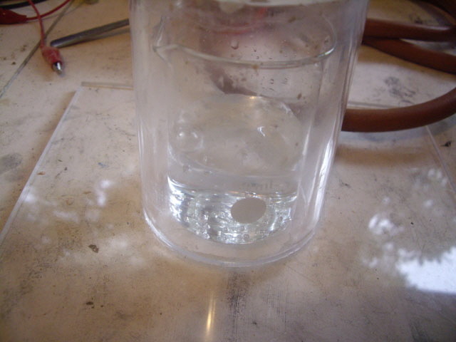
Figure 8. Water Boiling at 20°C under Moderate Vacuum
Another option is to try vibration. A hammer drill, an offset weight in a hand drill, or a simple hex should work. I machined both an offset weight and a hex vibrator but note that a bolt head will function just as well. I need to incorporate a PLA part in this test this so it’s time to build some new molds with the raisin clip.
Here’s a machining tip. To turn an eccentric the usual method is to offset the axial centre of the stock with a four jaw chuck and the tail stock. For this job a simple 1.5 mm spacer between the stock and one jaw of a three jaw chuck worked admirably.
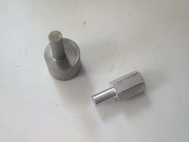
Figure 9. Drill Tools for Vibration Degassing
I glued the 3D prints onto masking tape stuck to a base board, and hot melt glued the forms in place. The forms are fractionally tapered which should aid with their release. The arrangement needs to be strong enough to prevent the parts coming loose and floating up in the slurry during vibration. And the form needs a water tight seal to the base board. The tape means that I can peel the base board off once everything has set without disturbing the investment. The paper will either fall off during oven curing or burn during firing.
The vibrators seem to work well. The hex tool produces a higher frequency lower amplitude vibration and seemed to be more effective than the eccentric tool. I simply held one end of the base board and placed the other on the vibrator tool, started the drill and adjusted the downward pressure on the base board for best effect. This was continued until bubbles stop rising to the surface.
I’ve left this too late in the day to remove the mold from the form but the tape peeled off fine. I’ll leave them overnight and complete removal baking and burn-out tomorrow.
The mold wouldn’t press out of the form despite the taper. Rather than cut the forms off and risk damaging the mold I ran a soldering iron down the side and they peeled off easily. Then it was into a convection oven at 110°C for an hour to remove any excess moisture. Then 20 minutes in my furnace to burn out the remnants of PLA. The mold has hardened nicely and there is no PLA or ash visible in the cavity but the shape of the raisin catch means that I can’t actually view this very well. I can clearly see that the investment has replicated the filament on the upper surface of the print so we should be good for casting. There are some hairline cracks and bubbles but these shouldn’t be detrimental to the final castings as excess can be filed true.
Time for casting! I’m going to do the molds one at a time so I have a reserve in case I make a silly mistake. The part is so small that I figure that I can dispense with a gate and feed directly from a runner which should also act as a riser. So I just need to fashion a pouring basin, sprue, well, and runner.
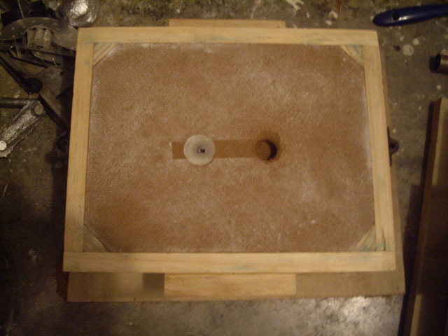
Figure 10. Drag with Investment and Sprue Well
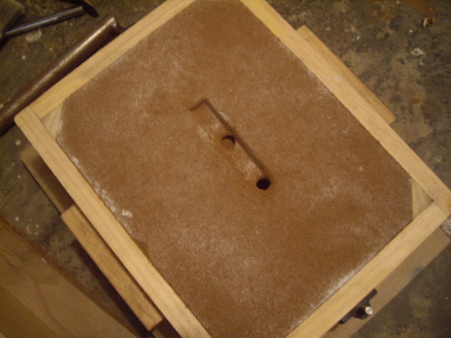
Figure 11. Cope with Runner, Riser and Sprue
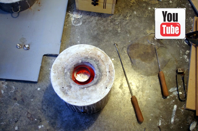
Figure 12. Aluminium ready for Pour
(Click on image for YouTube video.)
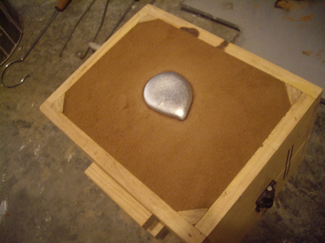
Figure 13. Pour Complete
Now wait 30 minutes for the exciting part...
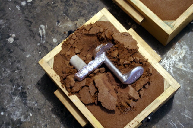
Figure 14. Breaking Open the Mold
(The investment has stood up really well without a single crack.)
The first part failed to form the raisin clip boss. I’m not sure where the error is. The investment appears to have worked without any cracking. Perhaps it is due to air dissolved in the aluminium?
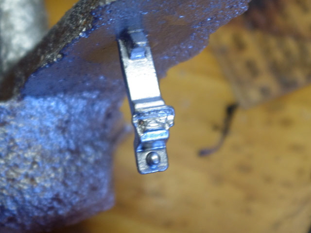
Figure 15. Boss Failure
Best I try the second mold and see how this goes. Darn, the same problem has occurred but by gently fracturing the investment I have found the cause. The investment has actually got inside the 3D print. I need to modify the print with increased infill (from 30 to 50%), improve the sealing, and maybe modify the part orientation for better print quality. If nothing else this is a testament to how good the investment is. It has migrated into a really small space and stayed there thought the drying, melt out and burn out phases of my process.
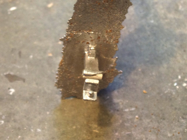
Figure 16. Second Attempt with the Reason for the Boss Failure Uncovered
While I’m about it I’ll add some material to the part to make it easier to separate from the runner. I also found another error. I had incorporated 6% for the thermal expansion of aluminium in the last print. Oops, this is the volumetric ratio, not the linear ratio! I’ve adjusted this to:
24E-6 m/(m °C) x (660°C - 20°C) = 0.0154 ~1.5% linear expansion.
I’ve also tweaked a few of my 3D printing parameters. The first layer height and width have been adjusted to 150% and 120% respectively. I have also adjusted the Z offset by -0.05 mm to ensure first layer adhesion to the bed. And I’ve increased the number of outer layers from two to three.
3D printing doesn’t produce perfectly flat surfaces and the parts are always porous. While sanding and solvent smoothing can help the improvement comes at the cost of effort and dimensional stability. Another useful technique is painting or dip-coating. But with this application the parts are going to be burnt out. The investment has faithfully reproduced the rough surfaces in my initial print. For my next effort I am going to try light sanding, solvent smoothing and filling surface imperfections by hand with wax from a coloured crayon to see if this improves the finish.
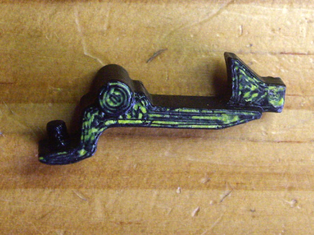
Figure 17. New 3D Printed Part with Crayon Infill
The 3D printed parts were printed, sanded, solvent smoothed, mounted, set in the investment, died and burnt out as before. The investment set really quickly suggesting that I may not have added sufficient water. Heating times were drying for 60 minutes at 110°C, melting out at 120 minutes at 231°C and burning out for 20 minutes at about 600°C. This took an entire day. The finished molds look good. The investment seems to be performing really well – but the test will be at the completion of casting.
One of the two parts was cast. Aside from two apparent air bubble defects (which were ground off with a Dremel) and some minor surface imperfections the part should be quite functional and is a reasonable facsimile of the 3D printed part.
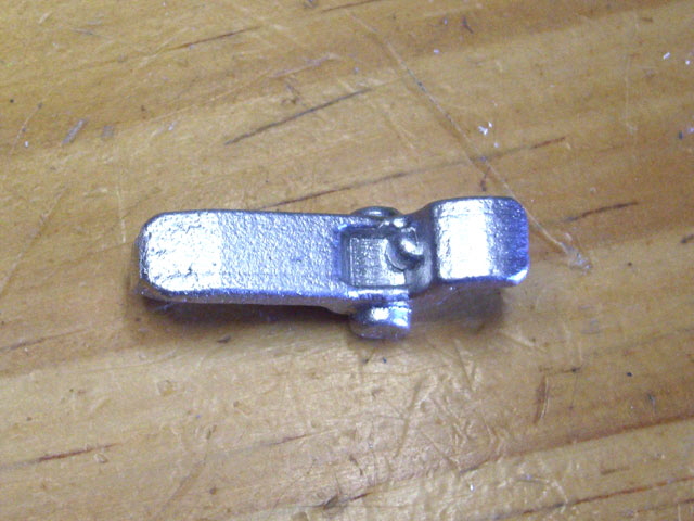
Figure 18. Bubble Defect as Cast
(Scale: Part is 29.6 mm long)
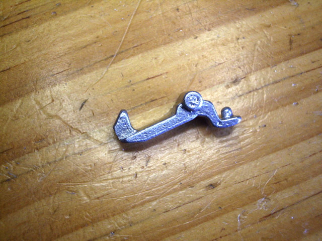
Figure 19. Finished Part Profile
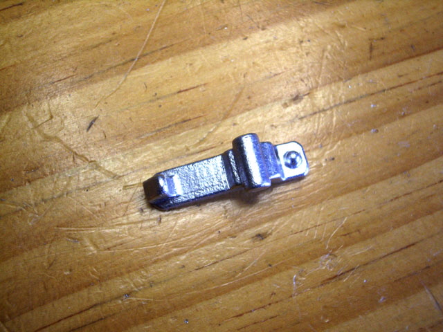
Figure 20. Finished Part from Below
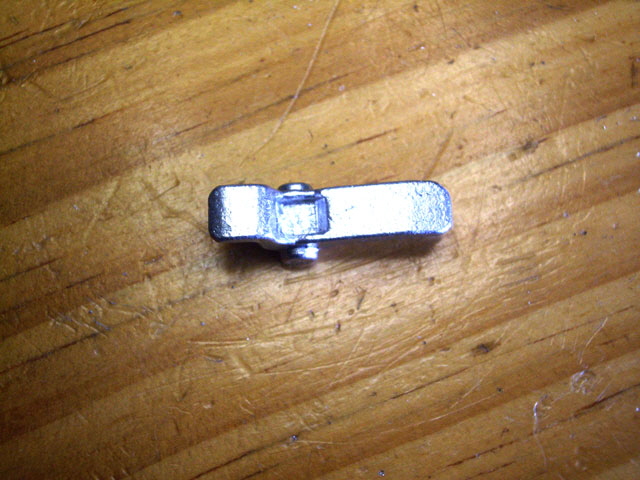
Figure 21. Finished Part from Top
(Bubble defect ground out.)
I’ve got a spare investment mold so I thought I’d section it and see what the cavity actually looks like. The investment is somewhat brittle but quite soft so I sanded away one half of the mold. This leaves the sectioned edges a bit rough but the PLA has gone entirely. There is one bubble defect apparent (see arrow in the following Figure) but otherwise the cavity has nice clean surfaces and appears to be true to the 3D print.
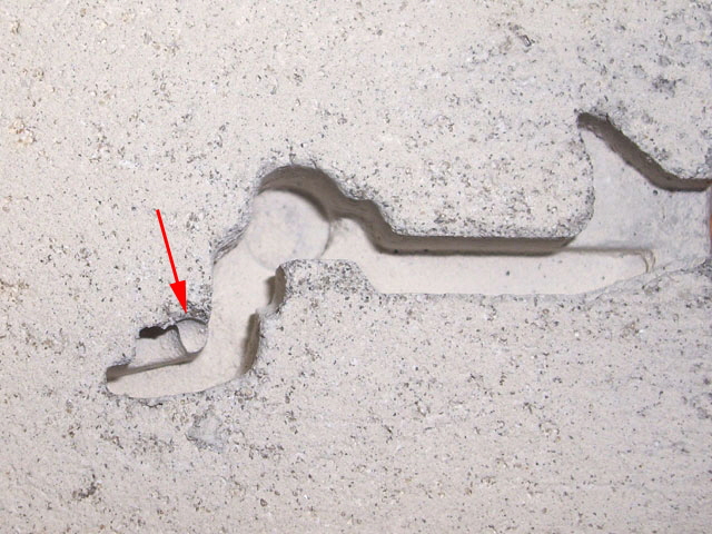
Figure 22. Sectioned Investment
(Bubble defect indicated.)
While the part looks good, and was fully functional in the bread maker without any adjustments to the casting there are some improvements that I can make to the process.
- The 3D print artifacts have carried through to the finished part so my crayon experiment didn’t work as well as I’d hoped. There is scope for improvement here - maybe dip-coating?
- The two air bubbles suggest that the investment mix set too quickly before the bubble removal by vibration. Maybe a little more water or using really cold water in the investment will improve this.
- There is some slight thinning of the thin walls near the axle boss. I figure that either the metal should have been hotter and/or the gate should be adjusted to the end of the boss. Some of the sharp corners have ended up slightly rounded and under-poured. This also suggests that the metal wasn’t quite hot enough. Maybe a longer sprue might be required to increase the hydraulic pressure in mold?
- The casting pour basin (on top of the cope) is too large and does not slope toward the sprue. This could be improved to reduce metal cooling in the basin and make the process more efficient.
- The part could be moved a lot closer to the well, reducing metal cooling.
But the basic process is working. I think I’ll have another go at casting my polar bear in aluminium.
I’ve already made my bear model and it looks really good as a 3D printed part in PLA. I followed the same process that I used for the raisin clip. Solvent smooth the 3D print, setting it in an investment block, melting out the bulk of the PLA, burn out the mold, and cast.
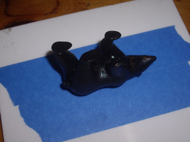
Figure 23. Bear 3D Print
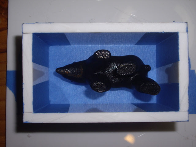
Figure 24. 3D Print in Investment Form
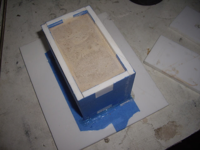
Figure 25. Investment Poured, Vibrated and Set
During burn out the larger investment block developed some hairline cracks but these did not cause the investment to fail so I continued to the pour. The cracks are due to differential heating of the investment, shrinkage of the plaster, and a lack of temperature regulation in my gas fired furnace. Perhaps adding some glass or carbon fibres to the investment will reduce the incidence of cracking?
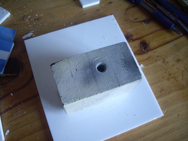
Figure 26. Investment Burn Out with Minor Cracks
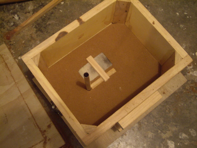
Figure 27. Sprue, Runner and Gating
There were four major defects with the finished part. Two were sink marks which are likely caused by inadequate risers, and two were caused by inadequate sealing of the 3D printed part. The surface finish was nice although it could be improved.
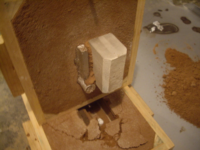
Figure 28. Opening the Mold
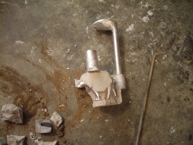
Figure 29. Looking Good
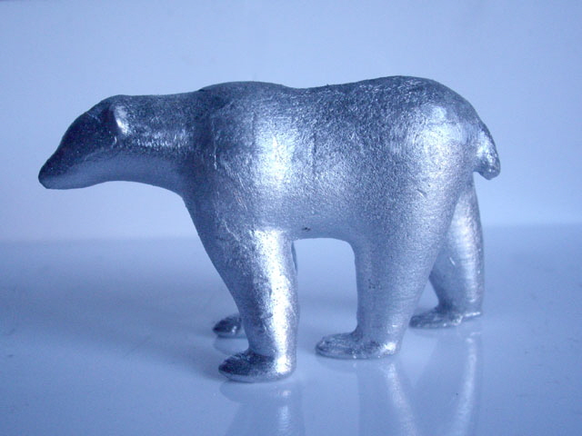
Figure 30. This Profile is Great ...
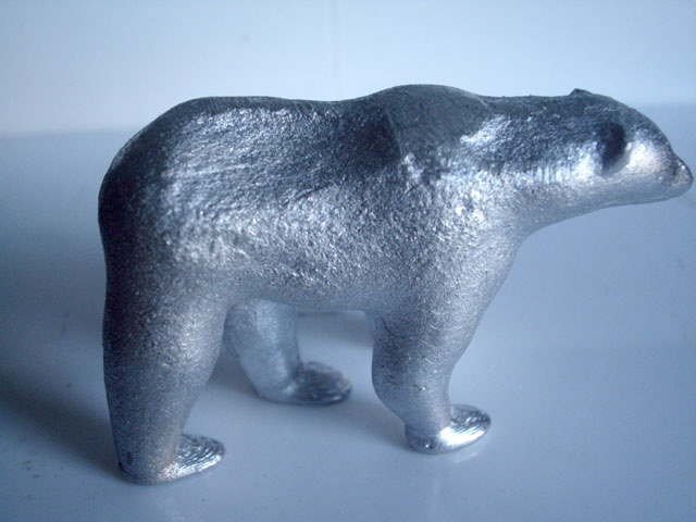
Figure 31. ... but we have Sink on the Other Side....
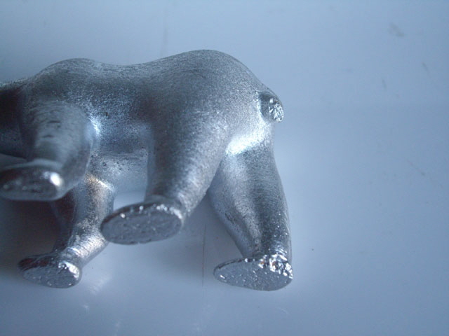
Figure 32. ... and Investment Inclusion in the Tail and Hind Foot.
If at first you don’t succeed adjust something and try again. This time I coated the 3D print in PlastiKote spray paint as a sealer filler, and added two risers right off the high point of the part. Unfortunately the paint formed a tough coating during the melt-out, and left ash in the part after burn out that I couldn’t remove. Even though I had reduced the furnace temperature the mold still developed hairline cracks.
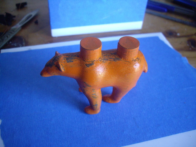
Figure 33. PlastiKote with Larger Risers
There was no point in casting with the ash in the mold so I split it open for inspection. With the exception of the ash, the mold surface is smooth with numerous really tiny air bubbles. The investment mix wasn’t great here and small lumps of unmixed sand were evident in the fired investment. Better mixing is required next time.
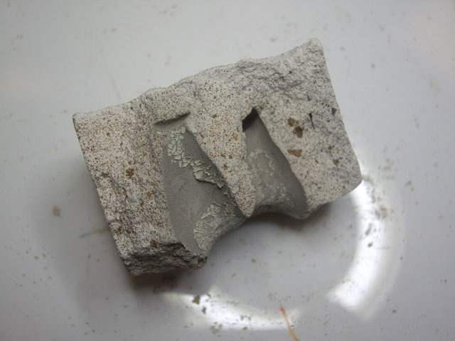
Figure 34. PlastiKote Ash Adhered to Investment after Burnout
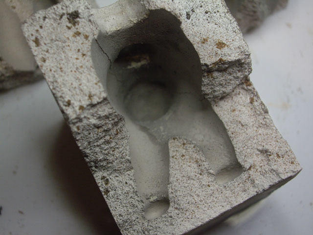
Figure 35. Smooth Mold Cavity with Ash in Left Foot
(The large crack at top left was caused during splitting of the mold.)
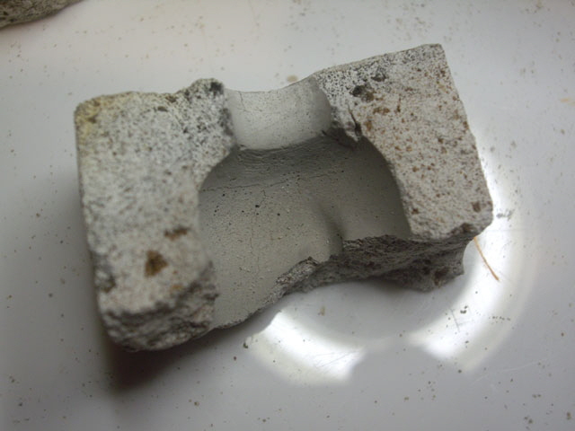
Figure 36. Hairline Cracks in Investment
So I need a different paint for a sealer filler. Let’s try Acrylic as a starter, sand off as much of the excess as possible to achieve a smooth finish and minimize ash while retaining the part dimensions. I’m also going to spray the 3D sealed print with Silicone to hopefully reduce adhesion between the investment and the paint.
I’m thinking that I can increase the sand ratio in the investment mix as opposed to incorporating fibres to reduce the incidence of cracking. Sand should be pretty much stable at the burn-out temperature but the plaster shrinks and cracks. We only need sufficient plaster to coat and bind the sand grains. At the moment there seems to be a significant excess of plaster. At 1:2 plaster:sand the water reduces to about 1 part by volume.
During the melt out (232°C for a couple of hours) I noticed that some of the Acrylic paint came out with the PLA as small fragments. This is good. I was interested to see how much of the PLA the melt-out removed. Based on weight the melt out is removing more than 80% of the PLA leaving less than 2 grams in the mold cavity.
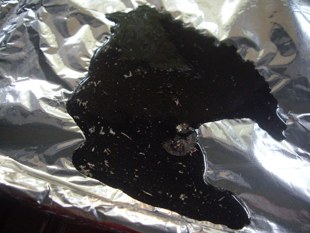
Figure 37. PLA Melt Out with Chips of Sealer
The Acrylic test failed again after burn out firing due to paint residue stuck to the investment. The white flakes turn to powder and might be mechanically removed but it is impossible to access the mold recesses.
The change to 1:2:1 plaster:sand:water by volume definitely reduced cracking during burn-out firing of the investment. I’m not sure if the Silicone had any useful effect, other than making for easy removal of the investment forms after initial setting. Here is the mold split open.
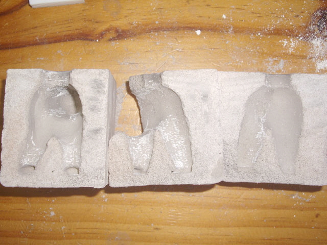
Figure 38. Mold Split with Acrylic Paint Residue
(Close but no cigar.)
The problem with the Acrylic paint is not the Acrylic but the pigments and fillers which are left behind in the mold. I need a paint without pigments or fillers. I have some clear water-based paint (Resene Aquaclear urethane/acrylic) in my paint supplies. A steel test strip dipped in the paint burns absolutely clean so this should do the sealing job without any residue. The data sheet for this paint states that the dried coat is thermoplastic which should melt out without char.
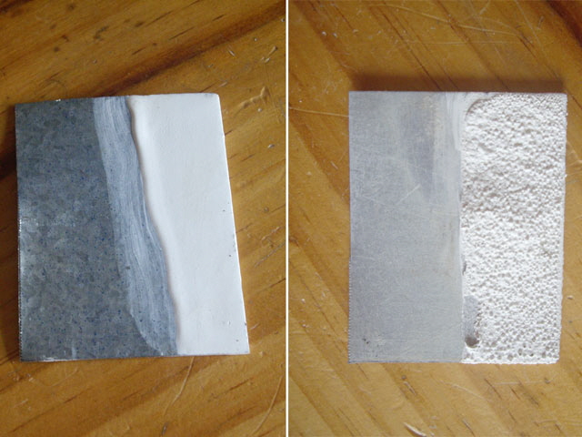
Figure 39. White Acrylic Paint Burn Test
Residue in pigment and filler than reduces to powder on touch.
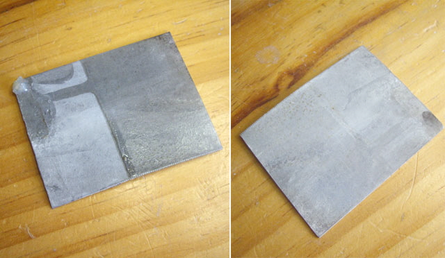
Figure 40. Resene Aquaclear Paint Burn Test
Absolutely no residue after firing.
A question you might be asking is why I am bothering with all this. About 45 years ago in high school I wanted to cast a cylinder block and valve housing for a steam engine of my own design. I made the patterns but simply ran out of time to complete the casting in the academic year. I suspect that the project would have failed, even with a successful casting because I didn’t fully appreciate the mechanics of the valve and the physics of steam expansion at the time. If I can cast my bear then chances are I can cast the major parts for a steam engine and tick this off my bucket list. I don’t have the original patterns but I figure I can design and 3D print these quite easily.
Another question that you might ask is why is this process so finicky. I guess finicky is relative. Real wax investment casting involves two molding steps (one to form the wax model and a second to actually cast it) and the application of investment is done in layers which is tedious and process sensitive. Even making sand casting patterns out of wood is exacting work requiring relief angles, parting and sealing. While these processes become more efficient for batch production they are not necessarily well suited for one off castings.
I’ve 3D printed out another bear ready for sanding, solvent smoothing, and an Aquaclear sealer dip coat. My first attempt at dip coating failed. The paint beaded and dripped off the PLA. Looks like the paint is not compatible with PLA and/or I hadn’t allowed enough time for all of the ethyl acetate used in solvent smoothing to evaporate. I tested the paint with an old PLA 3D print and the result was much better with good coverage and sealing and at least moderate adhesion. I suspect that I should do away with solvent smoothing. I re-sanded the bear 3D print and got reasonable results on the second attempt despite one paint drip.
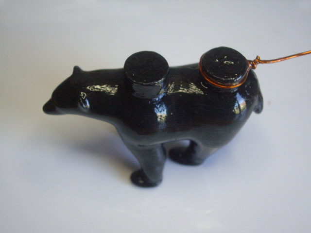
Figure 41. Aquaclear Coated 3D Print
I cast the investment, dried it at 110°C for an hour, skipped the melt-out (probably not a great idea) and fired it in my furnace for 30 minutes. There were no external cracks in the investment.
It’s really hard to inspect the finished mold cavity without a boroscope, but there is some carbon or plastic residue, the walls aren’t completely smooth, and there is at least one internal crack. But the base of the feet look to be clean so rather than consign the mold to the bin I decided to complete the casting.
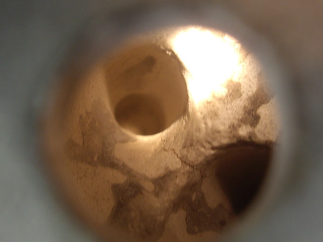
Figure 42. View Inside the Fired Investment
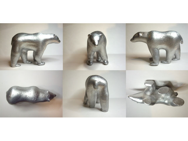
Figure 43. Profiles of Casting
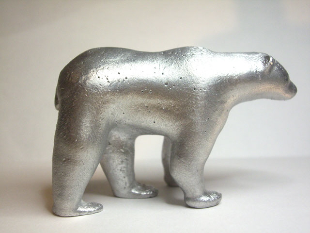
Figure 44. The Finished Polar Bear in Aluminium
(Overall length approximately 70 mm weighing 68.15 g.)
There are some minor shallow pinhole surface occlusions, a slight depression on one side of the belly, and a minor investment egress fault on one of the feet, but the casting is sound. Examination of the cutoff risers and gate showed solid sections. The bear stands securely on its feet with no rocking. I could probably cut out these defects with some surface finishing but for now I’ll leave the casting with a simple wire brush burnish.
I need some more experimentation with sealers (this will have to wait until after Covid-19 Level 4 lock down), re-institute the melt out, and maybe try using some clean aluminium alloy (perhaps with a higher silicone content for improved flow).
But I’m quite pleased with this result. The casting process should be quite adequate for my steam engine parts where there will be a machining tolerance on critical dimensions.
Job done.
|