|
The XK7113D has no hardware limit or homing switches (although there is provision for four active low home inputs on the controller card). While this isn’t necessarily a problem it does mean that the machine coordinate axis is not defined and can be expected to vary every time the machine is turned on. This also increases the risk of inadvertently crashing a milling cutter into something. There is plenty of space on the linear rails beside the motor coupling and the front bearing on each axis to mount an adjustable homing micro-switch without having to disassemble the machine. If the switch modules were mounted at the motor end of each drive then the wiring can be run back in the stepper motor plastic shroud. Manufacture should be a relatively straight forward 3D printing exercise if I can just find the sectional dimensions for the linear rail. They are a Hiwin HG15 type with a basic 15 mm x 15 mm profile outline. I have contacted Hiwin who immediately sent back a .STEP model of the rail. Thank you Hiwin!
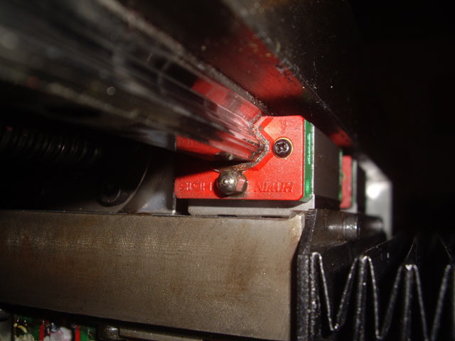
Figure 1. Hiwin Linear Rails and Bearings with Grease Nipple
(On the basis of this photo I have a lot more cleaning to do.)
Note: The Hiwin data sheet for their linear motion products contains some useful advice for life, load and lubrication of their linear bearings. The HG15 series should be lubricated with lithium grease every 100 km (about 400 hours of machining at 4 m/min) or 3 to 6 months. Their expected life is 50,000 km at rated loads. This is well over 25 years of continuous use!
Note: The standard X and Y axial directions appear to be rotated 180 degrees about the Z axis from what might be considered a conventional Cartesian coordinate axis view. While the stepper motors can be reversed by simply swapping one of the windings on the stepper motor driver modules don’t do this. (I did, and then had to revert to the origin wiring). The ‘issue’ is simply one of reference frame. Think of the diagram as spindle movement relative to the bed as opposed to bed movement relative to the spindle. When the bed is moving to the right (X-) or towards the rear (Y-), the fixed spindle motor is actually moving in the opposite direction relative to the bed!
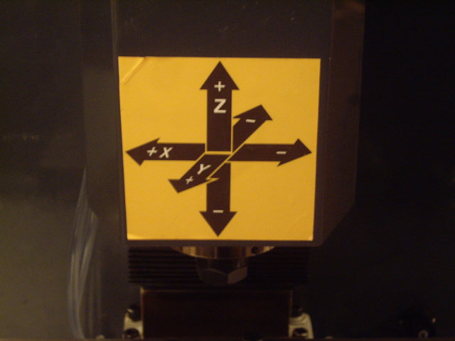
Figure 2. OEM Axial Directions of XK7113D
Home Switch Blocks
I need to make the homing switch blocks for X, Y and Z. I’m waiting on some appropriately rated micro switches before printing out the rail mounts. They are on order. The design was completed after a bit of trial and error.
The initial design was based on a hard wired cable back to the controller card. However wiring the switches back to the control cabinet was challenging with this arrangement. I redesigned the switch blocks using true micro switches with a double split spring mechanism and incorporating a miniature polarized JST socket to ease wiring and fitting.
The new design requires a machined plunger (in silver steel or brass) to actuate the micro switch. While I might have used a lever action micro switch the use of a lever actually reduces the sensitivity of the switching mechanism. The switch has enough spring force to return the plunger in any orientation so an external spring is not required. The part is 3D printed from PLA. While I initially contemplated gluing the socket and micro switch in place these are absolutely secure without adhesive. All machine screws fit to brass threaded inserts. The homing switch block is strong, light at just 8.6 grams, fits easily and securely on the linear rails, and is compact (with an identical cross section to the linear bearings).
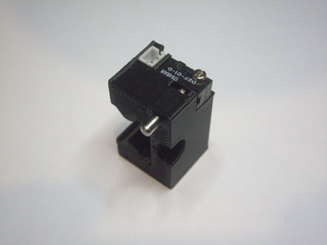
Figure 3. Homing Switch Block for X, Y and Z Axes
Fitting and adjustment of the homing blocks is very straight forward. Route the shielded cable to the control cabinet in the existing cable armor and connect to appropriate terminals on the control board. Fit the shielded cable plug to the switch block. Place the switch block over the linear rail with the plunger facing towards the linear bearing. Slide the side clamp between the rail and the switch block. Now manually home the axis (the switch block will actuate and move to the axis dead stop). Back off the axis and tighten the M3 clamping grub screw.
With the homing switch blocks In this position they will always actuate just before the full extent of the axis travel (providing maximum machining area). And they cannot be driven down the rail or damaged in the event of inadvertently trying to drive an axis beyond the hard end stop.
The Y axis fitting required some trimming of the plastic that holds the bellows onto the slide rails and one of the steel plates. However this has not been detrimental to the function of the bellows as they sit down flush with the frame under gravity. The bellows modification simplifies removal and re-fitting which is necessary for lubrication of the linear bearings.
Refitting the Y axis bellows mounting machine screws was a bit of a challenge. They holes in the bellows do not have adequate clearance to ensure alignment fit the threaded holes in the X axis carriage. I suspect that I have may have partially stripped one of the threads. I’ve enlarged the holes on the bellows to ensure ready alignment.
With the homing switch blocks in position I set up the Config, Home/SoftLimits parameters in Mach3.
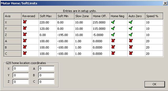
Figure 4. Mach3 Home/SoftLimits Parameter Setup
The XK7113D now auto-homes and zeros under Mach3. All of the traverses meet the machine specifications (even with the home switch blocks installed on the rails):
Note: RefHome under Mach3 always lifts the Z axis first so the spindle cannot reasonably crash into the fourth rotary axis if this is fitted. But an offset zero MUST BE SET relative to the fourth rotary axis BEFORE moving to zero. Failure to do this may slam the spindle or the tool into the fourth rotary axis.
Note: Set the Soft Limit switch in Mach3 to on. This prevents trying to drive the axis beyond the limits of the axis traverse once the machine is homed and auto-zeroed.
Note: Mach3 cannot detect if you manually turn the stepper motors. Use the Mach3 jog controls and home offsets (G54 to G59) to zero the tool to the stock relative to the machine origin.
Note: The homing speed is fully adjustable in Mach3 but you don’t want this set too fast because it will affect the accuracy of the home switch activation. Full traverse speed (66 mm/s) risks overdriving the switches and doesn’t allow time to anticipate a crash and react. I have the homing speed set at 10% but this could easily be increased too 20%.
Here is a short video clip showing the XK7113D auto-homing and zeroing to the home switch blocks and rapidly moving to zero. Click on the image to get to the YouTube video.
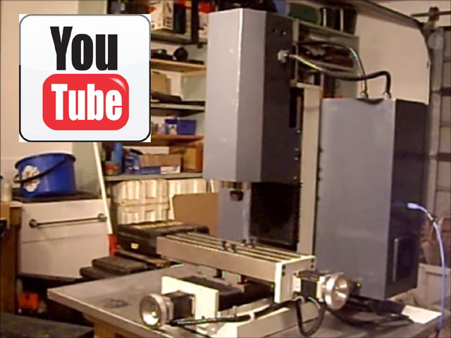
Figure 5. RefHomeAll and GoToZero under Mach3
Click here to link to the 4th Rotary Axis.
|