|
It’s time to try 3D printing some gears. I could start with something really simple like two equal sized spur gears but I need a compact reduction drive for the stepper motors I’m using on my coil winder development so I’m going to try a helical planetary reduction gear with a 1:4 ratio.
Plastic gears are used in all manner of stuff now days but these are usually injection moulded parts with superb tooth form and good strength. It will be interesting to see what I can achieve on my M2 printer.
I could make herring bone gears but this complicates assembly because you cannot assemble herring bone gears axially. So I’ll settle for helical gears and incorporate any necessary thrust washers in the design.
The first challenge is to model the gears. They need to be large enough to print with sufficient tooth accuracy and strength, but of comparable size to the motor body. I’m going to start this project making a gear set that is too large for the final application to be sure I can achieve adequate resolution and strength for a working gear train. This allows me to use a reasonable tooth size of about 3 mm (the exact dimensions are to be determined). Once the gearbox is working satisfactorily I should be able to scale the parts to achieve the desired final size.
It is possible to print a gear train fully assembled and literally break the gear points of contact into motion but I’ve decided to print the parts individually and avoid the problems of ceased printed mating parts entirely.
I’ll be using PLA for the gear box but nylon may be a more effective filament for gears due to its very low coefficient of friction and being somewhat softer with greater toughness and less brittleness. The only non-printed parts will be the machine screws that hold the case together, the thrust washers (if these are needed), and the stub axles.
I do most of my model development in Autodesk Inventor. This has a handy auto gear generator accessible for assemblies but for this project I’ve decided to draw the gears from scratch using appropriate parameters and clearances. I expect that the gears will run in so backlash can be zero provided the gears actually mate. Obviously the gears must be designed to prevent interference but this will be subject to the print accuracy. If necessary I will hand finish the gears for best fit.
Making the Model
Circular gears are designed with three primary objectives:
A reduction or increase in speed or torque (you can’t get both, ever).
A change in directional sense.
A change in drive angular and/or axial position.
The purpose of this gear train is an increase in torque (resulting in a loss speed) with no change in drive sense, position or angle. I figure that a torque increase of four (less gear train losses) should suffice.
The basic gear train looks like this (but you can change the number of planet gears depending on the dimensions). The pitch diameter (PD) of each gear is the rolling contact diameter of a circular wheels which can be imagined as gears with infinitely small teeth.
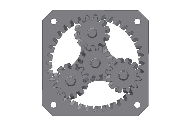
Figure 1. Basic Gear Configuration
The ratio of PDs determines the gearing ratio. For gears that mesh the ratio of PDs will be identical to the ratio of the number of teeth. But for a given pitch diameter the number of teeth is somewhat arbitrary subject to load considerations.
For a planetary gear train there are six drive/driven ratios available for given PDs depending on whether the sun, planet gear carrier or ring gear is held stationary, and which gear is driven. Note that the directional sense of the driven shaft will also depend on which gear is held stationary.
|
Input
|
Output
|
Stationary
|
Ratio
|
|
Sun
|
Carrier
|
Ring
|
1 + Ring / Sun
|
|
Sun
|
Ring
|
Carrier
|
- Ring / Sun
|
|
Carrier
|
Ring
|
Sun
|
1 / (1 + Sun / Ring)
|
|
Carrier
|
Sun
|
Ring
|
1 / (1 + Ring / Sun)
|
|
Ring
|
Sun
|
Carrier
|
- Sun / Ring
|
|
Ring
|
Carrier
|
Sun
|
1 + Sun / Ring
|
|
Additionally, if we lock any two of the sun, carrier or ring then the output will be a direct drive from input to output.
Driving the sun gear (input shaft) with the planet carrier as the output produces the best reduction ratio, with the input and output turning in the same direction.
The gear reduction ratio for this configuration is (1 + Ring / Sun) : 1. I want a reduction ratio of 4:1 so the ring gear PD must be three times the sun gear PD. I’ve also decided to make the planet gear PD the same as the sun gear.
Many CAD programs provide a gear generator but some of these use approximations to an involute or cycloid curve, and fail to allow for potential tooth interference. It’s been more than 40 years since I drew gears with pencils and pens on a drafting board but the procedure is relatively straight forward, if not a little tedious – and drafting ink is awfully unforgiving of mistakes. But I’m going to get the tooth profiles right by drawing them from scratch.
I’ll start by drawing the ring gear because this will have the most teeth and its diameter will determine the size of the overall physical size of the gear train.
I selected a ring gear pitch diameter of 45 mm which is an integer multiple of three. The ring gear PD is somewhat arbitrary but it will produce a nice sized ring gear for my prototype, and the integer multiple sets the sun and planet gear PDs to 15 mm.
Now select the number of ring gear teeth which will also determine the number of planet and sun teeth. This also needs to be an integer multiple of three or the planet gears won’t mesh. More teeth results in a smaller and weaker tooth profile, but too few will result in a clunky drive. I’ve selected 36 ring gear teeth so the sun and planet gears will have 12 teeth:
36 teeth / 3 = 12 teeth
Now on to drawing the model.
I’m going to make this description brief because there are a heap of text books on engineering drawing and you will find the interweb is full of video tutorials specific to drawing gears in various CAD programs. I do apologize for the fact that the following compressed screen images don’t have sufficient resolution to see detail but you should get the general idea of the process.
Draw a circle at the ring gear PD.

Calculate the tooth circular pitch (CP) on the PD: CP = pi * PD / No. ring gear teeth.
We can now calculate the addendum and dedendum which are the height of a tooth above and below the PD. I’m using teeth proportions from the British Standard for a 20° pressure angle:
Addendum (ADD) = 0.3183 * CP
Dedendum (DED) = 0.3979 CP to 0.4538 * CP (let’s say 0.4 CP)
Draw two further circles concentric with the pitch diameter with diameters equal to PD - 2 * ADD and PD + 2* DED. Note that on a ring gear the addendum is inside the PD and the dedendum is outside the PD which is opposite to that of a spur gear profile.
Note that most CAD programs will let you do the maths directly with reference to other dimensions. This is not only efficient and accurate but it means that if you change a base dimension all dimensions calculated from it will change appropriately.
Add a reference vertical centre line to the concentric circles.

Figure 3. Addendum and Dedendum form Tooth Tip and Base Profiles
Choose your tooth pressure angle. I’ve selected 20° but there may be good reasons for choosing other angles depending on the size of your gears, the tooth circular pitch and the application.
Now draw a line at the pressure angle below horizontal from the intersection of the PD and the vertical reference axis.

Figure 4. Pressure Angle Drawn from Top of Pitch Circle
From the centre of the PD draw a fourth circle tangent to the pressure angle line. This circle is the base circle with a diameter BD for our tooth involute curve profile.

Figure 5. Involute Base Circle Tangent to Pressure Line
Now do a circular copy of say 8 instances of the pressure angle line at say 5° increments about the concentric centre.

Figure 6. Circular Copy of Pressure Angle Line
Now calculate the circumference of 5° of the BD: BDC5 = pi * BD * 10 / 360.
In many CAD programs you can simply draw a line, dimension it, and then assign the dimension of the line using the above as this formula (subject to syntax).
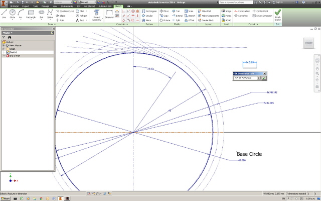
Figure 7. Using Formula to Determine Circumference of 10° of Base Circle
At each successive intersection of the copied pressure angle lines we draw a circle of diameter:
n * 2 * BCD5, where n is an integer, 0, 1, 2, …
In AutoCad Inventor we can use our calculated reference line to dimension these circles as integer multiples. This saves a heap of calculating and transferring dimensions.

Figure 8. Drawing the Involute Locus Points
The intersections of these circles and the pressure angle lines form the points on an involute curve starting at the vertical axis. Draw a smooth curve (spline perhaps) between the intersections extending above the ADD and below the DED circles and trim the curve (spline) back to these.
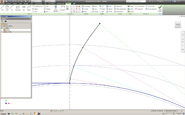
Figure 9. Drawing the Involute Curve as a Spline
If your involute base circle diameter, BD, is greater than ADD then you won’t be able to extend the involute curve below BD. You can either adjust the pressure angle, add more gear teeth, or simply extend the root of the involute on the BD to the centre of BD, and trim to the DED.
Note that there is no need to fillet any acute teeth corners for 3D prints because these will be rounded by at least the diameter of the extruder nozzle.
We can now mirror the involute about an axis, rotary offset the copy with an allowance for clearance if required, followed by a further rotary copy to complete the gear profile. Be aware that that with some CAD software (including Autodesk Inventor) when you copy a spline each copy will have different constraints which may change the the profile. If this occurs then you will need to investigate the fixing which will be software dependant.

Figure 10. Mirrored Involute to Form Other Side of Tooth
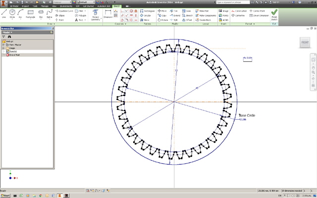
Figure 11. Rotate, Copy and Add Tooth Tips and Roots
Extruding the ring gear profile give us a spur ring gear.

Figure 12. Extruded Spur Ring Gear
We can now draw the planet gear using exactly the same procedure used for the ring gear, but noting that the addendum is now outside the PD and the dedendum is inside.
We aren’t quite done as we haven’t looked at potential interference between the ring gear addendum and the planet gear dedendum. This is best addressed by copying and rotating either gear about its own axis in say 10° increments, followed by a negative rotation of the same gear through the same angle, reduced or increased by the gear ratio, about the other gear’s rotated axis. In essence we are holding the planet gear stationary, rotating the ring gear around it, and plotting the path of the the ring gear addendum corners. This is quite straight forward but it takes some thinking about.
The locus of the ring gear addendum corners provides a profile that ensures there is no interference between the gears.

Figure 13. Double Rotation of Ring Gear Addendum about Planet Gear Root Profile

Figure 14. Ring Gear Addendum Locus from Double Rotation
Now simply adjust the tooth profile of the planet gear below the PD to the locus and mirror it to complete the planet gear tooth profile.
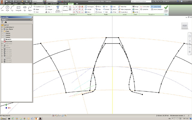
Figure 15. Planet Gear Tooth Profile
Finally circular copy to form the planet gear profile. This will also be the sun gear profile in this design because the two gears have the same PD.

Figure 16. Circular Copy to Form Planet (and Sun) Gear Profile
Add a centre hole to the gear profile and anticipate over-drilling this for a precision running fit on an axle.
Once we have the gear profile then we just need to extrude this to the desired thickness to make a spur gear. To make a helical gear I use the coil function in Autodesk Inventor. Remember that the helical pitch must be the same angle but with an opposite sense for mating planar helical gears.

Figure 17. Helical Planet Gear
With the model completed in Autodesk Inventor it was exported in STL CAD format, imported into Simply3D, and sliced for 3D printing to produce the printer gcode instruction file. This process takes just a few minutes and we’re ready to print.
3D Printing Time
The first print took some time at high resolution (over an hour for the planet gears, the sun gear and the two carrier plates) but the results were simply amazing. The planet and sun gears mesh perfectly on the stub axle centres with no perceivable backlash or interference. Holes in the carrier plates are a perfect press fit for the stub axles. The planet gear axle holes need to be over-drilled to 5.1 mm for a close running fit on the 5 mm diameter stub axles.
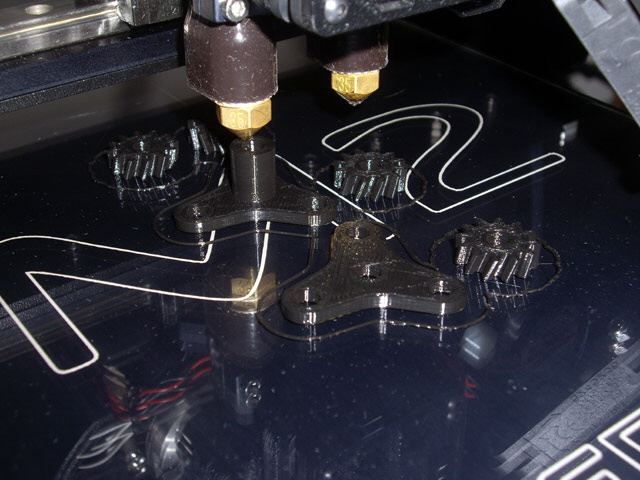
Figure 18. First Gear Print
When drilling holes in PLA use sharp bits, a low cutting speed, lubricating oil and peck drilling, otherwise friction between the drill and the part may cause sufficient heat to melt and deform the part and once this starts the problem will compound.
The next print was the ring gear and back plate which were far from perfect. There was a problem with the model resulting in an issue with the case wall that I didn’t pick up in Simplify3D until after the print. The corners of the print had also lifted off the heated bed which is a recipe for distortion. But the critical failure was with the ring gear action. The gear did turn but it was far too tight and bordering on impossible to mesh.
My first thought was to run the gear in with a hand drill drive but this failed to fix the tight mesh and created another problem. One of the planet gear stub axle ends hadn’t been finished dead flat and cut through the base plate surface layers. Bugger!
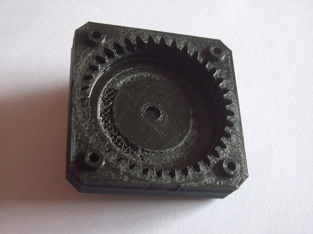
Figure 19. Woops! Case Cut by Stub Axle
I took some dimensions and the ring gear appears to be only fractionally small (0.2 mm). I figure that this is due to my model alignment problem and the possibly of filament width rounding in the Simplify3D slicer. My extruder is 0.35 mm, the critical ring gear dimensions are not multiples of 0.35 mm.
I re-drew the model as a simple ring gear without the integral base plate and increased the bed temperature from 65 to 70°C to overcome the bed adhesion issue. I checked the dimensions in Simplify 3D by scaling off the monitor and we were good to print.
The new ring gear print was flat to the bed and dimensionally sound but the planet and sun gear fit was just as bad as the original??? On further inspection something is wrong with the ring gear helix angle. No wonder the ring gear doesn’t mesh. The helix angle between mating helical gears should be the same. I went back into the model and looked at the parameters that specify coiled extrusions. I’ve specified an identical revolution and height for the gears but the ring gear revolution clearly needs to be divided by the planet to ring tooth ratio.

Figure 20. Ring Gear Helix Pitch Angle
(Black: Planet Pitch. Red: Ring at Planet Pitch. Green: Ring at 1/3 Plant Pitch.
We had a red ring gear pitch. We need green. )
So I’m going to be printing another ring gear. Whoot! The ring gear engagement is still fractionally tight but the full reduction gear now assembles and operates without undue force.
I clamped up the gearbox in a drill press with the chuck driving the gearbox reduction output shaft and set it running at 660 RMP (the input shaft rotating at 2,640 RPM). The gear ran just fine for the five minute test with no adverse wear, noise, vibration or heat apparent. There was no backlash or slop apparent after the run-in. After the wear-in the action is still a little tight but smooth.

Figure 21. Prototype Planetary Reduction Gear
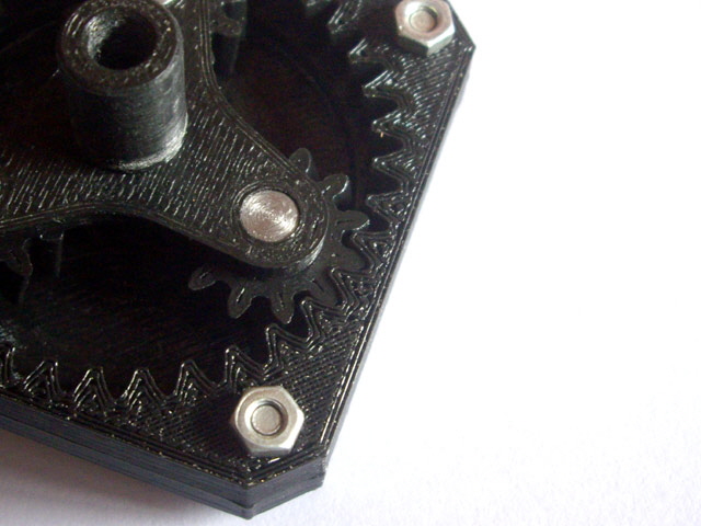
Figure 22. Mesh Detail
Now all I need to do is to scale the gears to fit the stepper motor case and adjust the mounting machine screw spacing. The size reduction factor is 0.75 which gives a tooth depth of 2.1 mm. This should be more than adequate for this application and should print within the available resolution.
While my prototype had a secondary carrier plate my earlier test shows that this is not necessary and, if anything, increases friction in the gear train. I have removed it. With appropriate case dimensions there is no need for thrust or spacer washers in this application.
The final gear box required a few reprints to correct ‘my dumb’ mistakes.

Figure 23. Scaled Gearbox Parts
I wrote some quick and nasty code to drive my stepper motors 4 revolutions and 1 step (0.225°) forward, followed by 4 revolutions backward. This ensures that, over time, the gear will be fully exercised. I programmed the stepper motor speed as fast as it would go (about 150 RPM) without stalling under moderate finger load. Note that if I reduce the stepper motor speed the available torque increases significantly so that I cannot cause the output shaft to stall by hand. I won’t be trying to use a tool because this will cause something to break.
Time for a warning for really stupid people. Gears (even plastic gears) are a potential pinch and crush hazard. While an accident is unlikely to be fatal, sticking your fingers between rotating gears is likely to be an unpleasant experience. This ‘toy’ gear train has sufficient mechanical advantage to drag a digit into the mesh where the weakest part will be compressed and deformed until something breaks or the obstruction passes through the engagement. If you must try this to see if I am right use a sausage or piece of cheese (either a reasonable approximation to flesh).
The gear train was run in on the stepper motor over 250,000 revolutions (24 hours) with a very fine abrasive (I used metal polish but toothpaste would do) applied to the gear teeth and mating surfaces. All components were then cleaned and inspected with no adverse wear apparent. The gearbox was re-assembled with molybdenum grease lubrication.

Figure 24. Click on the Image for YouTube Video Link.
(The gear runs perfectly, even without the planet carrier.)
The finished part is completely functional, dead quiet, has no perceivable backlash or axial slop, and gives me all the torque I will ever need for my winder. The final gearbox size is 42.3 mm square (to match the motor body section) x 8.7 mm thick. I have kept the original motor mount which adds a further 3 mm to the thickness of the gear box but this could easily have incorporated in the gearbox casing print.
I reprinted the planet carrier with a slightly longer output shaft tapped at M6 x 1 for the spool axle on my coil winder. The spool axle is fixed in place with a drop of super glue.

Figure 25. Gearbox Installed in the Coil Winder
I’ve subsequently 3D printed a whole bunch of other gears with pitches down to just 1 mm and they work beautifully. Job Done
|