|
I’ve already made a gear pump on my Makergear M2 FFF 3D printer. It actually pumps liquid and air but, like all FFF prints, it leaks like a sieve through the pump casing. Let’s see if I can take this same model water and air tight using my Saturn 2 SLA printer.
The first issue that I had was with the dimensions of the original model. They had been adjusted to compensate for the relatively poor resolution of my M2. I had to rework the model.
The next mission was to print out the pump parts. These were my very first SLA prints on my Saturn 2 (even before the rook). I had a few problems including elephant’s footing, and Z dimensional accuracy. It took a lot of wasted resin before I finally had usable dimensionally accurate parts.
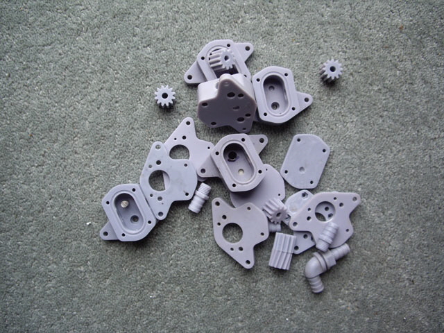
Figure 1. Lots of Failed Prints and Design Iterations
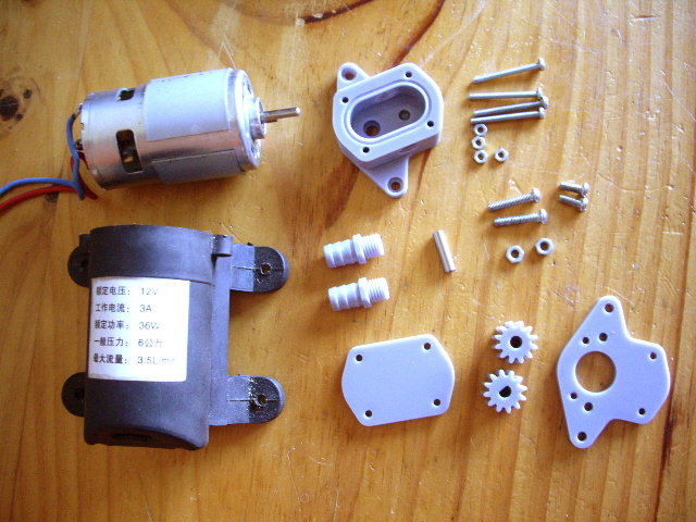
Figure 2. Accurate Parts ready for Assembly
I was using Elegoo water washable ceramic gray resin but this wasn’t a great choice. It was too brittle and had a very limited working temperature range. During my experiments I kept on breaking the hose fittings. So I changed to Elegoo ABS-Like ceramic gray and altered the hose fitting dimensions. This improved the strength, but not the temperature limitation. I now have some high temperature Siraya Tech resin but I’m holding off on the reprint until I’ve completed my tests.
The gears were run in on the motor using toothpaste and machine oil until there was no decrease in motor current at 2 V. This is hardly lapping compound but it seems to do the trick.
Video 1. Running In
(Click on the image to view on YouTube.)
The pump was assembled without any issues in the following sequence.
- Fit the motor shaft seal O ring in the recess at the base of the case.
- Push in the four M3 nuts on the motor mounting plate.
- Mount the motor on the plate with two M4 machine screws.
- Press fit the idle gear shaft into the recess at the base of the case. Note that I had previously glued this in place with super glue as I made a design error with the recess diameter, hence no picture.
- Fit the driven and idle gears (previously run-in with toothpaste and machine oil).
- Fit the gear pump case to the motor mount and secure with two M4 machine screws.
- Fit the cover O Ring seal in the case recess (I printed this from Nijaflex using my FFF Makergear M2).
- Fit the cover using four M3 machine screws (I added some flat M3 washers as an after-thought).
- Fit the barbed 8 mm hose fittings.
I measured the motor current during construction, all at a motor terminal voltage of 2 Volts. The bare motor draws 0.86 A. This is way off the motor specification from the data sheet and is significantly greater than the original pump motor which drew about 0.9 A at 12 V. This is what comes of buying really cheap motors from (country unspecified to keep the peace). But note that running with no load the new motor consumes significantly less power than the original motor.
With the motor shaft seal fitted the motor current increased to 1.75 A. This is higher than expected but could likely be reduced with less O ring seal compression. I figured slightly too much compression was better than a major leak disaster caused by too little.
With the pump fully assembled it is drawing 2.2 Amps at 1,635 RPM pumping air.
It was time to see how the pump performed with water. I attached some 800 mm long pieces of 8 mm ID PVC hose to the pump. The barbed fittings were a perfect press fit for the hose.
The pump:
did not leak,
readily self-primed at 300 mm suction head,
was very quiet and didn’t vibrate compared with the diaphragm pump that it is intended to replace,
provides continuous (as opposed to pulsating) flow,
was reversible by simply changing the polarity of the motor,
has no spring loaded valves (each a significant hydraulic loss) , and
with fluid circulating, didn’t get warm, yet alone hot.
The unrestricted flow rate at 2 V drawing 2.67 A and running at 1,724 RPM was slightly over 2 litres per minute. At 4 Volts drawing 4.75 Amps the flow rate was 4 litres per minute at 2,538 RPM. The flow rate appears to be quite linear with motor voltage as expected.
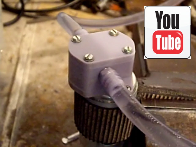
Video 2. Motor Test
(Click on the image to view on YouTube.)
The pump is only providing about 70% of the calculated flow rate per revolution. This is likely due to the clearances between the two gears and between the gears and the case; the offset intake and exhaust ports; and the abrupt geometry in the flow path (sharp edges).
Typical efficiencies of commercial gear pumps are up to 85%. I haven’t calculated the pump efficiency yet but I suspect that it’s well down on 85%. I also haven’t measured the churn (no flow) output pressure yet, but holding a finger over the outlet hose creates a high velocity jet which will be perfect for my spray nozzle. And still there is no pump leakage, even running the pump at 6 Volts!
I ran the pump continuously for over an hour with no appreciable change in characteristics. So the pump looks like it will be usable for its intended purpose, pumping water soluble cutting fluid for my machine tools, even though it is not made from a high temperature resin.
The pump has been working on and off for several weeks now for periods of up to an hour and the motor current has gradually increased to about 4 A at 2 V.
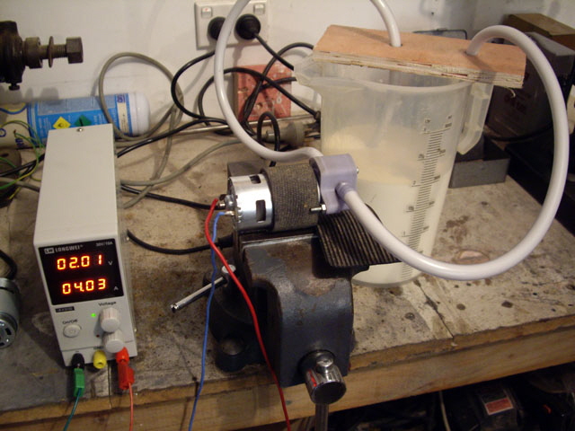
Figure 3. Testing with Soluble Cutting Oil
I pulled the pump to pieces and inspected it. There is a problem with the motor mount and the base of the casing which have distorted. The O ring seal is also way too tight on the motor shaft and has started to degrade. There is also some wear on the casing from the gears but I suspect that this is from the original running in.
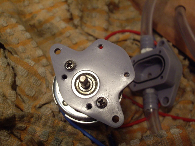
Figure 4. Heat Warped Motor Mount
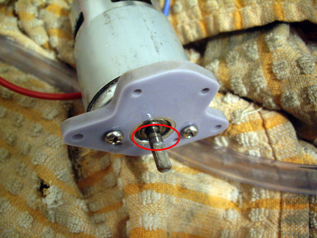
Figure 5. O Ring Seal Debris on Motor Shaft
I suspect that what has happened is that I failed to account for resin shrinkage in the initial build. As a consequence the motor shaft seal has ended up with too much compression on the shaft. So the motor and shaft start to get warm under the increased load which has caused the plastic to distort, making for a cyclic path to disaster. This should be readily fixed by using a higher temperature resin and allowing for resin shrinkage.
A late consideration suggested by others was the potential for the 3D printed plastic parts to softening and swell in the cutting fluid. Most plastics will absorb water and goodness knows how they will react to the oil. I measured and placed some of my failed prints and put them in cutting fluid for 17 days. They had expanded by about 0.2 mm, and the gear had developed an inter-layer adhesion crack (likely at a print fault), but they had not softened.
As the parts dried out of the next few days the gear and the top cover developed severe cracks which isn’t good at all. But the hose fitting was completely fine. I am left wondering if this is the effect of water or oil and why the gear was destroyed but the hose fitting wasn’t. The dimensional stability is a problem.
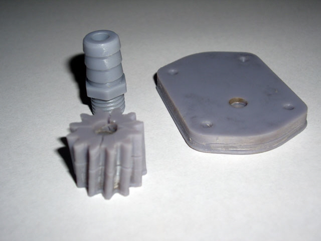
Figure 6. Not Good! The Elegoo Resin doesn’t like Soluble Cutting Oil
I’m going to try my Siraya Tech resin with thermal stress relief prior to and after curing to see if I can resolve these issues. Interestingly water absorption seems to be quite resin specific with some performing rather poorly and others rather well (<1% w/w over 24 hours immersion).
I’ve remade the gear pump using Siraya Tech Build smoky gray resin, incorporating a number of modifications including tapered threads on the hose fittings, improved clearance on the motor shaft seal.
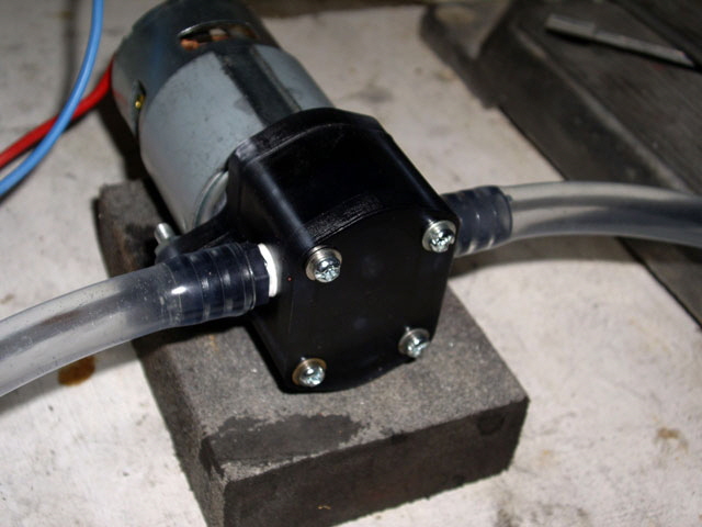
Figure 7. Siraya Tech Gear Pump
The pump performed almost identically to my previous print in Elegoo ABS Like Gray resin with a gradual increase in current from about 2 Amps to over 4 Amps over 24 hours of continuous duty pumping water with 2 Volts at the motor terminals.
On pull down the only sign of appreciable wear was on the ends of the gears and the mating case and cover bearing surfaces. These are actually quite rough. I believe that the issue is the relatively high coefficient of friction for plastic running on plastic (say 0.8 but likely higher for SLA prints). The plastic isn’t polished by this action but seems to degrade by fine tearing. But the wear isn’t surprising as the circumference of the 20 mm diameter gears has traveled over 130 km in 24 hours at about 1400 rpm.
I suspect that this wear is the main cause of the current increase over time. So I decided to try a further modification, adding steel bearing washers in the case and case lid for the gears, and increasing the idler axle length to 21.5 mm. The coefficient of friction for plastic on steel is about half of that of plastic on plastic, and the steel won’t wear appreciably. So the friction should be reduced and, if it increases at all, this should be relatively gradual, hopefully with a polishing action on the plastic.
With the new pump assembled, and run in it was drawing 1.7 A at 2 V pumping air. Pumping water the current increased to about 2.2 A, but interestingly the motor speed has increased to about 1,500 RPM (previously about 1,440 RPM).
After 24 hours of continuous duty the current had increase to 2.8 Amps and the speed had reduced to about 1450 RPM. The motor temperature was just above ambient and there were no leaks. The flow rate was measured at about 1.75 L/min. I pulled the pump down and the new washers had worked beautifully. There were no cracks or distortion apparent in the printed parts.
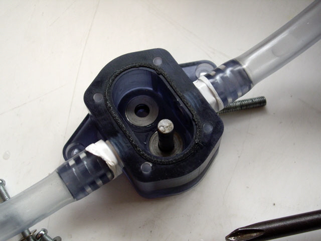
Figure 8. Case in Good Order after 24 Hours Duty
(Note bearing washers)
But the motor shaft seal was causing problems again with O Ring rubber stuck on the motor shaft. And when this was removed there appears to be a wear ring on the shaft. This may have been caused by my earlier seal failure but if needs to be sorted out to make a functional pump with a reasonable service life. This will need some more research and experimentation.
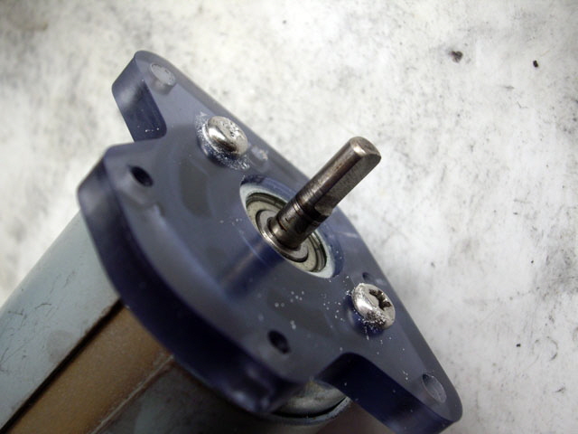
Figure 9. Another Shaft Seal Failure
While all of this has been going on I completed some further soak tests of the Siraya Tech and Elegoo resins. After seven days immersion in water the Siraya Tech had had increased in weight by 2.3%. The Elegoo had increased by just 0.8%. On drying the Siraya tech developed minor surface cracks but neither resin showed signs of swelling or softening, so they’re both likely good for use with water.
The Siraya Tech resin performed much better than the Elegoo resin in cutting fluid, with no distortion, softening or delamination apparent. But on drying it developed the same hairline surface cracks as it did with water. One thing I didn’t do was thermal stress relief of the parts before and after curing. Perhaps this might help?
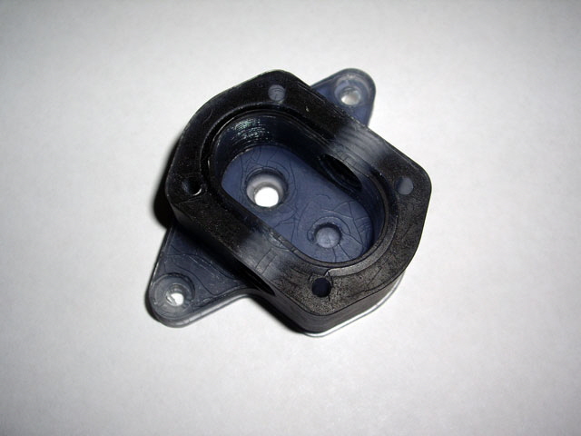
Figure 10. Siraya Tech Cutting Fluid Immersion
(Note hairline surface cracks on drying.)
After reassembly, a quick test with water and following standing for 48 hours the Siraya Tech pump had ceased. The problem I am experiencing is that as the resin absorbs water it expands, reducing the clearance between the gears and the casing and increasing the compression of the shaft seal. As a consequence there is a gradual increase in motor current until the pump eventually ceases.
Most real plastics have a saturation limit. They might absorb say 0.8% of water (by weight) in the first 24 hours but the rate of absorption decreases over time to the saturation limit which might be a few percent. But I’m thinking that 3D printed parts just keep on absorbing water due to there layered structure.
I could increase the clearances but that’s not good for the efficiency of a positive displacement pump. So I’m going to try a centrifugal design where there is just one moving part (the impeller) and clearances, while still important, aren’t as critical as my gear pump.
I designed a small centrifugal pump to fit my existing motor, printed and assembled it. The impeller design wasn’t engineered - a simple open impeller design with vane shapes based on a logarithmic spiral that looked about right terminating in an inductor blade at the inlet. I partially assembly the pump and, with safety glasses on, ran the impeller at full speed to see if it was going to fly to bits. It passed this test. On assembly the pump is definitely working pumping air so I moved to water.
A week of testing and the pump performance gradually degraded and it eventually ceased. On disassembly the impeller had failed (likely due to swelling resulting in contact with the case) and the O ring shaft seal was causing problems again.
I redesigned the impeller to a closed design with slightly thicker walls a additional clearance, and I purchased some small dynamic shaft seals for a few dollars to overcome the O ring shaft seal friction.
|