|
My first steps in this process were to make a gas fired furnace, a suitable crucible and an LPG burner. There are numerous web pages that will give you inspiration and much of this design has been based on these sources.
I want to be able to melt about half a litre of non-ferrous metal and alloys (say 4.5 kg of Copper, 5.5 kg of Silver or 1.3 kg of Aluminium). This will require an upper of temperature of about 1,200°C. I plan on using a steel crucible about 80 mm internal diameter and 100 mm tall. I figure on using about 100 mm thickness of refractory and about 15 mm clearance between the crucible and the refractory (this space is essential for the flow of hot gas inside the furnace cavity and I have subsequently discovered - 15 mm is simply not enough – 50 mm would be better).
The furnace was constructed in a stainless steel cylindrical formers cut from a waste paper bin. The bin was sectioned to make the body and the lid formers using a Dremel grinder. Other cutting techniques are likely to distort the stainless steel. The overall dimensions of the furnace body former were 300 mm in diameter and 210 mm tall, and the lid former was 300 mm in diameter and 100 mm tall.
The furnace cavity was planned at 110 mm diameter x 120 mm deep formed around a nominal 100 mm PVC pipe (OD 110 mm) with one end closed with a 3D printed circular plate.
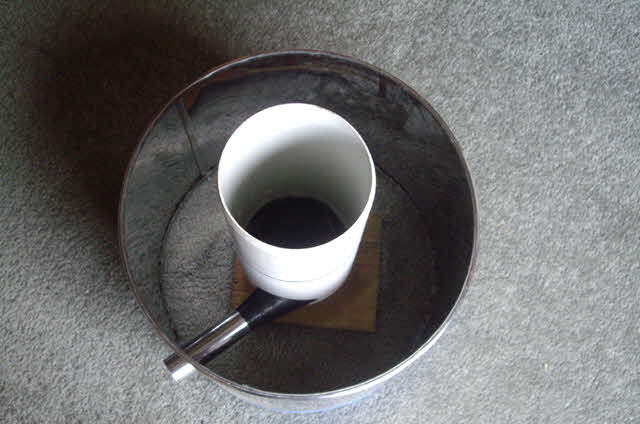
Figure 1. Furnace Forms
The burner was designed to fit inside a 25 mm OD thin wall steel tube with room for thermal expansion. The burner mounting tube was cast in the refractory located approximately 25 mm clear of the furnace cavity and extending through a hole in the body former. The tube was supported by another 3D printed part that formed a tangential flare entry into the furnace cavity.
The exhaust hole former for the furnace lid was made from a nominal 50 mm PVC pipe (OD 55 mm). I have no idea at this time if this is too small or too large. If it is too small it will create a lot of back pressure affecting the burner performance. If it is too large then it will waste heat.
For the refractory I settled on a mixture of expanded Perlite (available in five litre bags from a local hardware chain), Aluminium Oxide and a Sodium Silicate binder (the latter both available from a local pottery supply agent). If you can’t get these last two ingredients then you can make them from readily-available chemicals. You might also consider replacing the expanded Perlite with coarsely ground pumice.
I used the following mixture ratios for the refractory cement.
You will find other mixture ratios with more Aluminium Oxide and perhaps other additives (such as Magnesium Silicate). I figure that the quantity of water can be reduced to about 250 ml and the Aluminium Oxide content can be increased to about 1 kg. The mix looked great in the mixing bucket but when it was pressed into the formers a quantity of excess binder solution escaped from the around the base of the formers. Increasing the Aluminium Oxide retains more binder in the mix, but Aluminium Oxide has a relatively high conductivity (about 30 W/m.K) and we want thermal insulation.
The optimum expanded Perlite density for minimum high temperature conductivity is about 128 kg/m3. The material’s insulating properties come from the large number of tiny air cells in the expanded Perlite grains (which is why it is so light and fluffy). Dry air at 1,000°C has a conductivity of about 0.08 W/m.K. The function of the Perlite is to stop the air forming convection currents which can transfer appreciably more heat at high temperatures than conduction. Either an increase or decrease in the Perlite density results in increasing conductivity. With too little density the refractory will be generally porous allowing convective heat flow through the mass. With too much density the Perlite becomes the primary conduction mechanism with a conductivity of about 0.6 W/m.K.
The purpose of the Aluminium Oxide in the mix is to assist with coating the expanded Perlite grains to reduce the porosity of the matrix. The Sodium Silicate is a high temperature binder and sealer.
Mix the ingredients wet by hand in a large bucket with a dust mask on (Aluminium Oxide will form a dust cloud that you don’t want to ingest). When the mixture is about right it will clump together when squeezed with no excess moisture. Avoid vigorous over-mixing or the Perlite will be crushed into fines.
Set up the forms on plastic sheet and fill with refractory cement in 25 mm layers, applying light to moderate compaction to avoid overly crushing the Perlite. The furnace body has a volume of approximately 14 litres and will require about 35 litres of expanded Perlite (as a refractory mix) to fill the former for optimum conductivity. Place some weight in the cavity form or it may rise due to hydraulic pressure of the binder.
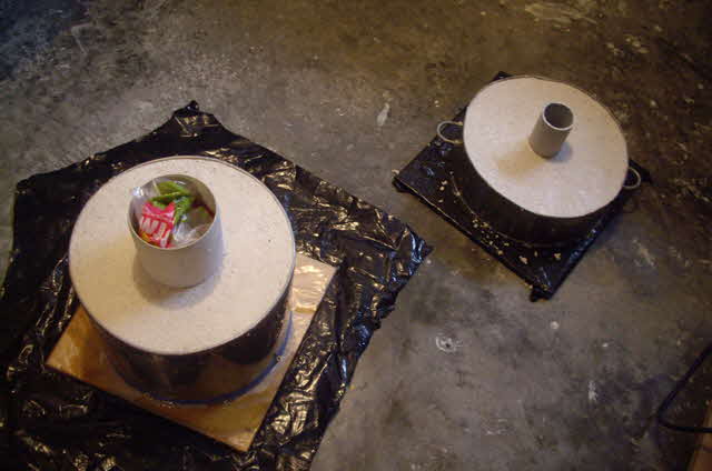
Figure 2. Refractory Cast
Now set the cast refractory forms aside for a few weeks to thoroughly dry. If the refractory isn’t completely dry when you apply heat it will develop cracks (more on this later). Note that Sodium Silicate is hydroscopic so if the relative humidity is high it simply will not dry.
It is winter here and the ambient temperature is typically between 6 and 10°C and the relative humidity has been quite high (up to 93%) in recent weeks. This is not ideal for drying the refractory, particularly when it is contained in impervious forms. I improvised a drying oven from an old dish washer body, the parts from an old fan heater and a plastic bucket. This maintains a steady stream of warm air at about 60°C through the drier.
My refractory has dried (or so I thought) and I gently removed the internal forms for the lid hole, the furnace cavity and the burner port by twisting and wiggling the forms.
Before lining the furnace I have decided to gradually bring it up to temperature to ensure that the refractory is thoroughly set. I expect that the refractory will begin to sinter at the end of the heating process. Initially the lid was separated from the furnace body with some pieces of 5 mm steel mesh which were removed later in the firing.
During heating there was a lot of steam driven off from the furnace so the refractory was not as dry as I had assumed. The refractory certainly sintered and turned a blue tinted white, but on slow cooling a number of significant cracks had formed. I figure that this is a consequence of insufficient drying. After the furnace had cooled down I drilled the cracks out to 5 mm width and filled them with more refractory during the lining process.
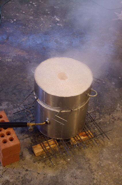
Figure 3. Steam During Initial Heating - Not Good!
(Note Burner is Original Primus for low heating.)
This first heating operation gave a visual indication of achievable furnace temperature. A black body radiator has a distinctive colour temperature and the furnace cavity as seen through the exhaust port is a good approximation to a black body radiator. Accurate colour rendition with digital photography is not straight forward but the furnace cavity got to bright orange (perhaps bordering on yellow). So I am confident that the temperature was comfortably above 1,250°C based on both the colour and the sintered expanded Perlite.
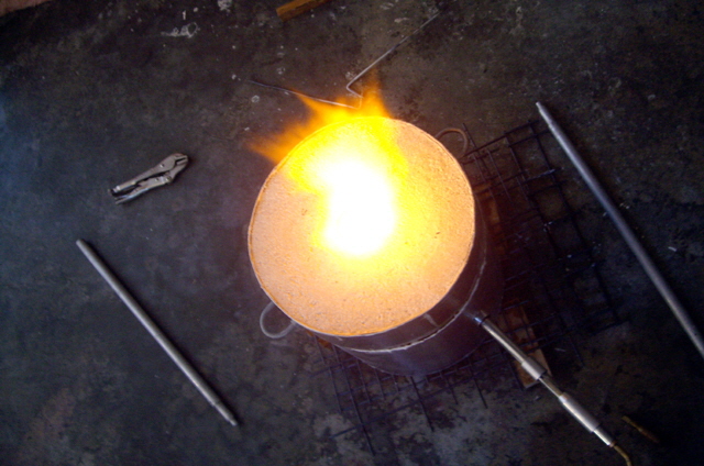
Figure 4. Flaring
(New burner with lid spacers removed.)
Flaring above the exhaust port is a clear sign of too much fuel or too little air. This is not particularly useful unless we are deliberately trying to operate the furnace cavity under reducing conditions because flame above the exhaust port does not contribute to heating of the furnace cavity. We want the combustion process to be neutral (neither reducing or oxidizing) and entirely within the furnace cavity.
Furnace Lining
We are now ready to line the furnace cavity with a high temperature refractory.
The lining is necessary to protect the Expanded Perlite from the anticipated temperatures in the furnace. Perlite begins to soften at about 1,000°C and will start to fuse about 1,250°C. Aluminium Oxide begins to melt at about 2,000°C and Magnesium Silicate at about 1,900°C.
Sodium Silicate softens at about 650°C and will begin to flow at about 750°C so you might be wondering how it can be used as a high temperature binder. At relatively high temperatures soluble silicates form a ceramic bond with clay type materials and metal oxides (magnesium in particular) with good post-firing performance expected to over 1,700°C. So our refractory lining must be fired to achieve the desired physical properties.
The lining is not a fantastic insulator (Aluminium Oxide is a relatively good heat conductor) but it doesn’t need to be. The lining simply protects the expanded Perlite from the furnace cavity gases and temperatures, and it can be readily replaced or repaired over time.
The lining is based on Aluminium Oxide, Magnesium Silicate and Sodium Silicate in the following proportions.
Aluminium Oxide: 1 part by volume
Magnesium Silicate: 1 part by volume
Sodium Silicate: 1 and 1/3 parts by volume
Mix the ingredients for form a thick paste about the consistency of cake frosting and greyish in colour. Apply with a spatula in a thin layer to the inside of the furnace cavity, the top of the furnace body, the matting face of the furnace lid and the inside of the exhaust port. To get a flat finish I sprayed the lining with a small amount of water and ran a trowel across the flats. The lining needs to thoroughly dry before it can be fired, otherwise it will blister and crack.
Once the lining is thoroughly dry gradually heated it with an LGP flame working over the entire lining surface. The lining developed blisters and fine cracks because it was not sufficiently dry. I chipped and filed the blisters and filled these, and the cracks, with further application of the lining mix. Now I need to set it aside to dry properly before re-fire the lining. This time I will try baking it in a domestic fan oven progressively increasing the temperature to at least 150°C over several hours before firing the lining.
Once fired the lining will be white in colour and brittle. Any minor imperfections can be sanded smooth, particularly in the burner port where we want unimpeded flow of burning gases.
Note: You cannot simply assemble the furnace and use the burner to fire the lining as the lid will almost certainly adhere to the furnace body and removing it will be difficult and damage the lining.
Firing in Anger
Okay, it’s time to see what we can achieve with the furnace. I lit the burner at a very low gas flow, inserted it in the furnace burner port, and set about gradually increasing the gas flow while avoiding excessive flaming from the exhaust port. The intention was to gradually increase the furnace temperature to avoid thermal shock while allowing any residual moisture to vaporize and transport through the refractory without causing spalling, all the while attempting to maintaining a neutral flame.
Note: Leather gloves, dark goggles, natural fibre clothing (not synthetic) and adequate ventilation, and clearance from other combustibles are sensible safety precautions. I operated the furnace almost directly below a ceiling-mounted dual mode ionization/photoelectric smoke detector (confirmed as fully operational). The detector did not go to alarm.
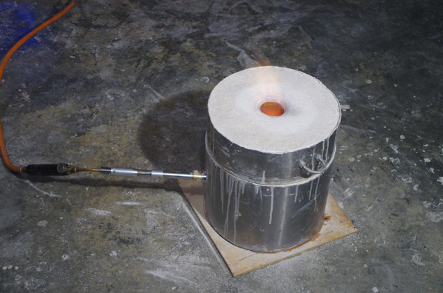
Figure 5. Initial Firing
On this initial firing there is no plan to actually melt a metal charge because I have not sorted out fluxes and degassing additives and I have no moulds prepared.
The furnace came up to maximum temperature in about 15 minutes. The cavity colour was bright orange to yellow. The outer shell eventually got uncomfortably hot to the touch after about 40 minutes.
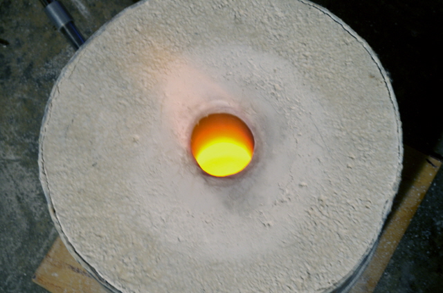
Figure 6. Colour Temperature
The burner remained cool throughout the firing. All of the burner adjustments could be altered by hand with no risk of burns.
The burner could only be operated at relatively low gas flow rates, even without a crucible in the furnace. High gas flow rates caused flame pulsing or excessive exhaust port flaring.
After an hour I turned off the gas and removed the burner. The cavity colour reduced to a deep red after 10 minutes and was still warm to the touch after four hours.
On inspection there were a number of fine cracks in the refractory lining and a collection of blisters, but nothing that looked like significant damage. The lining remained secured to the refractory (it would not chip or peel off). I filed off the blisters and filled the cracks with more refractory cement lining before the next firing. The cracks are clearly due to shrinkage and will have relieved the resulting stress.
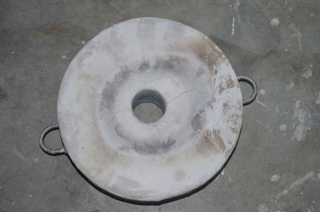
Figure 7. Minor Cracking of Lid
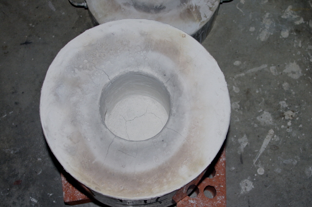
Figure 8 Minor Cracking of Body
I also disassembled the burner and found that one of the threaded joints was loose and there were was a minor blockage in the jet orifice. These issues will certainly have influenced the burner performance and were easily fixed.
Improvements
So we have had some success but the furnace really needs to be bigger. A larger furnace will:
increase melt capacity to at least one litre,
reduce direct flame impingement on the crucible,
allow for a larger burner flare diameter,
allow more clearance for the flame to circulate between the crucible and the furnace walls (the current clearance is clearly insufficient as it chokes the burner performance),
ease crucible handling, and
make lining easier (the current 110 mm furnace cavity diameter makes it very difficult to physically get at the bottom of the cavity and burner port for lining).
If we stick with our 100 mm thick refractory then we should be looking at a 400 mm diameter furnace approximately 400 mm high (with a cavity of 200 mm diameter and 200 mm deep). We will need some more formers and a lot more refractory but we can reuse our existing refractory by crushing it into the mix. A 60 litre oil drum will be an ideal former for the new furnace and lid.
I also want to add some reinforcing in the lid and at the bottom and sides of the furnace to make sure that the formers are securely bound to the refractory.
We will also need a new crucible about 100 mm in diameter and 150 mm tall.
I intend to work on the replacement furnace in slow time as the current model will let me start experimenting with sand casting (and maybe some investment casting) in the interim.
Please read on about some thermodynamic theory by clicking here.
|