|
Part printing orientation is important for a number of reasons. It can significantly:
- improve the strength of flexible parts (parts that are expected to bend or resist bending)
- reduce printing time
- save filament
- improve aesthetics
3D printing can be used to produce flexible parts but be aware that that part printing orientation can greatly reduce or improve the effectiveness and longevity of flexible parts.
The cover latch on the between-seat utility compartment in my father-in-law’s car broke. The latch was a relatively simple plastic part but a replacement required purchase of an entire utility lining at over $300. I offered to make a new latch for him.
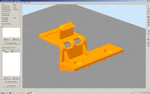
Reproducing the original design was quite straight forward. I modified this because it was clearly inadequate for the intended duty (the original part broke under fair wear and tear). I added some fillets, extended the bending radius and reduced the area of the bending section without compromising the locking function. The intention was to increased flexibility, reduce stress and improved longevity.

Figure 1. Latch Modified Design
My first 3D print looked great and fitted perfectly but after a few stress tests it broke near the the point of maximum deflection. The reason for this was the part printing orientation. The part deflection caused stress between the print layers causing de-lamination. See Figure 2 for original print orientation and Figure 3 for layer print detail at the point of failure.

Figure 2. Initial Latch Printing Orientation (Failed to perform)

Figure 3. Initial Latch Printing Orientation
(Note bending stress is applied between horizontal layers)
I changed the part printing orientation (to essentially that as shown in Figure 1) so the horizontal walls were normal to the de-lamination plane. Stress due to intended bending is now imparted through a bundle of continuous plastic beads printed in the horizontal plane as opposed to between horizontal layer junctions (Figure 5). I also incorporated additional solid planes (every 5 layers) in the infill to further strengthen the part. After literally hundreds of test deflections and mild abuse I could not break the new part.
- Orientate flexible parts so anticipated stress is in the horizontal plane. Stress between horizontal layers may lead to early failure through de-lamination.

Figure 5. Changed Orientation with Design Stress Through Continuous Beads
Click here to navigate to print quality problems (and maybe some solutions)...
|