|
The Quest for a Perfect First Layer
Let me state that at the outset that this quest is likely unattainable on a Saturn 2. I think I can get close, but not in sensible print times without accepting other compromises.
My thrust bearings on the lead screw of my Saturn 2 resolved the problem with ball screw axial play to within +/- 0.1 mm but the very first printed layer is still too thick at an estimated 0.30 mm when it should be 0.05 mm. This initial layer thickness doesn’t seem to be a ball screw axial play issue.
Figure 1. Axial Play Improvement in Z
The thick initial layer causes subsequent layers to be printed too thin until an actual print height of about 0.5 mm. The results were repeatable over two models (Calibration 7 and 8).
Changing the home position (Z=0) by varying the thickness of leveling card makes no difference to the initial layer thickness.
I’m going to make what some folk might consider to be a controversial statement. True Z=0 s with the build plate on the FEP on the LCD. It should not be at some unspecified two sheets of paper above the LCD. Some folk will swear by first layer height calibration in a full resin vat, or directly on the LCD, or by using various paper or card gauges. If these techniques work for their models then that’s fine. But they probably aren’t interested in the first layer’s actual height or accurate Z dimensions.
True Z=0 is with the build plate on the FEP on the LCD.
Here is an interesting link which discusses the issue of initial layer thickness with a focus on the Saturn 2 resin vat. This shows how the seating plane of the FEP (the top of the FEP) can be too high above the base of the resin vat.
So I made some measurements on my machine. The vertical distance between the vat-to-deck plane and the FEP seating plane was all over the place (but the measurements were repeatable). Here is a sketch showing what I found. The FEP seating plane was at least 0.20 mm above the vat-to-deck plane all around, and in places up to 0.28 mm.
My particular FEP is exactly 0.127 mm thick when new, but in use FEP stretches and gets thinner. The original FEP for my Saturn 2 was specified at 0.15 mm thick but when I replaced it due to damage it had reduced to just 0.10 mm - a 33% reduction. I can’t readily measure the thickness of my installed FEP but I’m going to assume that it has stretched and is now about 0.10 mm thick.
I also took some measurements between the deck of the Saturn 2 and the top of the LCD. The LCD was generally proud of the deck by up to 0.16 mm but this dimension was all over the place too.
The LCD edging tape was 0.13 mm thick.
I also checked the LCD for flatness. This was dead flat to within the limitations of my measuring instruments. At last we have a useful reference plane.
The final measurement of interest was the clearance between the resin vat and the Saturn 2 deck. This ranged from 0.00 mm at points of contact near the clamp screws to 0.04 mm along the entire back edge of the vat (adjacent to the Z column).
Putting all of these measurements together here is a sectional sketch (not to scale) that shows the maximum potential variation in the position of the FEP in relation to the LCD is only 0.06 mm assuming the surfaces are flat and parallel and the tape is remove. Unfortunately the surfaces aren’t flat and parallel.
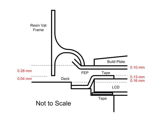
Figure 2. Sketch of Vat Section
The first issue to attend to was the LCD edging tape. The build plate cannot sit on the FEP on the LCD with this tape in place. The tape creates a pool of resin about 0.13 mm thick beneath the build plate. I removed the tape and residual adhesive off the deck. I used a strip of Kapton tape at the back of the LCD to provide some protection for the LCD flexible PCB and connector. The remaining three sides of the LCD were left open.
A better way of fixing this issue while retaining the tape would be to machine the build plate to fit within the inner tape perimeter. This won’t affect the build area and will reduce the hydraulic forces during retract. But for now it’s easier to simply remove the tape.
Addendum. After a number of further prints without the tape I’m finding strands of cured resin in the vat for otherwise perfectly printed models. I figure that this is being caused by low intensity light being reflected through the sides of the of the LCD (and protector plate). I’ve refitted the tape but just to the sides of the LCD (not overlapping). If this doesn’t fix the problem then I’ll be painting the edges of the LCD black.
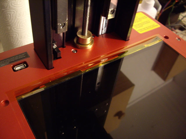
Figure 3. Tape Removed and Kapton Added
The next issue was to attend to the resin vat. The vat-to-deck plane wasn’t flat and the FEP seating plane was fractionally too high above the vat-to-deck plane. I sanded the vat-to-deck plane until it was level on a granite surface plate using 800 grit carborundum paper leaving 0.127 mm between the vat-to-deck and FEP seating planes all round.
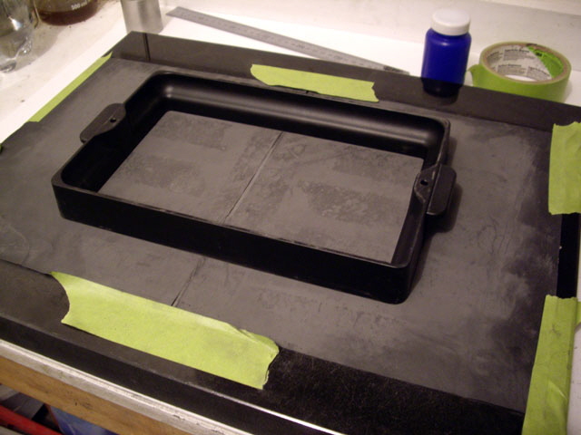
Figure 4. Adjusting the Vat Planes
I cleaned and reassembled the resin vat and checked that the FEP was in direct contact with the LCD. Then I homed the build plate onto the FEP (without resin in the vat) and set Z=0.
With the same calibration print the first layer height hadn’t measurably reduced. I know that I have Z=0 so the problem can’t be clearances. It must be the hydraulic force on retract for the very first layer. The viscous resin is being squished to a very thin layer across the entire area of the LCD, and its flow is restricted by the roughen surface of build plate.
The hydraulic force theory makes sense if you are at all familiar with velocity profiles of laminar fluid flow over a flat plate. At the surface of the plate the fluid doesn’t flow at all and the velocity increases to a maximum value some distance away from the surface of from the plate.
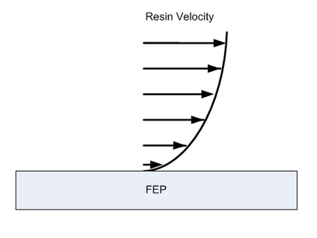
Figure 5. Laminar Flow Velocity Profile over a Plate
If we place another plate above and compress the plates together the fluid velocity becomes increasing limited by shear between the streamline planes in the resin as the distance between the plates decreases.
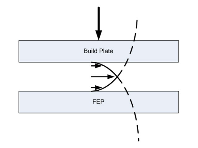
Figure 6. Thin Layer Flow Squished between Two Plates
Note: This thick first layer also creates the need for increased exposure time. If we can get the first layer closer to 0.05 mm then the required bottom layer exposure time should also decrease.
There are several solutions to this problem including reducing the resin viscosity, increasing the compression force, increasing the time for the fluid to flow, increasing the layer height, or relieving the hydraulic pressure.
The first two solutions aren’t very practical as they involve messing with the resin chemistry or perhaps increasing the temperature, and we are pretty much stuck with the build rigidity of the Saturn 2. But we can change the time between retract and exposure allowing more time for the resin to flow.
Note. Counter-intuitively slowing the retraction speed isn’t expected to help. While this does provide more time for fluid flow it reduces the driving force. Fluids such as paint, gels and likely resin have a property known as thixotropy. They tend to flow better when they are subject to increased stress. Fast retraction is therefore likely a good thing.
I could increase the first layer height, but surely a printer with a default layer height of 0.05 mm should be capable of printing all layers at that height?
So I increased the rest time before exposure of the bottom layers in 30 second increments to 300 seconds. Note while ChituBox forces these changes on all print layers the handy and free utility, UV Tools, allows you to modify this setting for just the bottom layers.
The increased bottom rest time before exposure resulted in excessive print times but the initial layer thickness progressively reduced from 0.27 mm down to 0.08 mm. But as the first layer height became increasingly thin mechanical deflections in Z (likely due to the linear rail blocks and Saturn 2 deck) started to appear in the print. We are therefore reaching the limits of the Saturn 2’s performance.
Figure 7. 300 Second Rest Time before Exposure
But perhaps my last potential solution will work? If I were to drill an array of small diameter holes through the build plate then the resin pressure can be relieved through relatively short 10 mm flow paths compared with the 225 x 130 mm surface area of the build plate. Any exposed resin in the relief holes will likely cure to form small nodules on the bottom of the print. These should be easy to remove on an otherwise flat model surface.
Why am I about to drill holes in a perfectly serviceable and somewhat expensive build plate? This is the only way I can test my hydraulic theory and if I don’t do it then I’ll die wondering. And in the event that it doesn’t work, you don’t have to.
I’ve ordered a new build plate so I can experiment with the old one. Note that the old plate with drilled holes will still be useful even if the holes ruin it by using a magnetic base.
I drilled four 0.9 mm diameter holes through the cast aluminium build plate centred on the corners of the upper rectangular plane. This is unlikely to be the optimum position but it’s near the centre of the plate, and I usually avoid printing there. Positioning models near the edges of the resin vat is preferable as it creates a peeling action during separation of the model from the FEP during lift.
I wanted to drill smaller diameter to holes and, if necessary, gradually increase the diameter but I also didn’t want a broken carbide drill bit stuck in the 10 mm thick build plate. My carbide PCB drills are just 8 mm long so I had to pre-drill 1/8” diameter 2 mm deep holes at the top of the plate for the carbide drill shank.
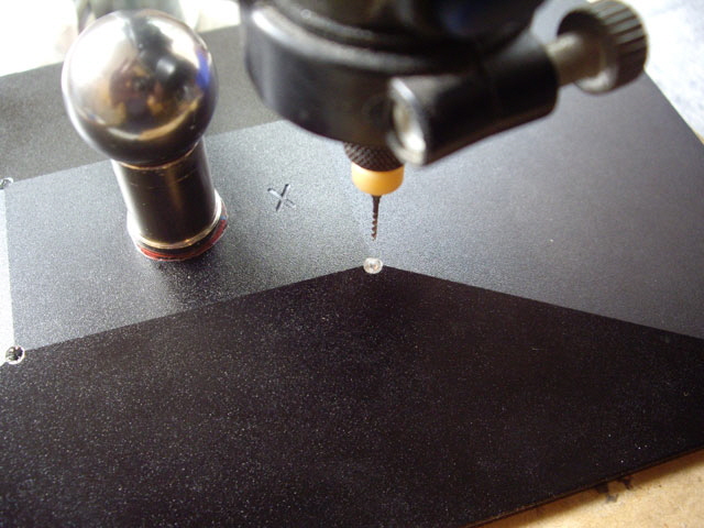
Figure 8. You’re Not Really going to Drill Holes Through a Serviceable Build Plate?
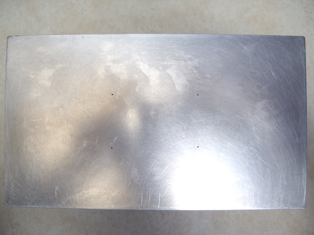
Figure 9. I Sure Am!
Time for another calibration print.
Note: before making this print I adjusted my calibration model scaling in X, Y and Z by 1.07 to account for resin shrinkage. This calibration factor isn’t quite right in X and Y and there is a reason for this which I shall explain in a later post. I also adjusted the layer height by the same factor to ensure that my slicer (Chitubox) didn’t start rounding layers up or down. I also reduced the bottom layer rest time before cure from 300 to 180 seconds, but I’m confident that I can reduce this even further.
The holes worked perfectly. During the initial retract resin oozed from the top of the holes over the build plate. On subsequent layers the resin flow rapidly reduced to zero.
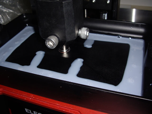
Figure 10. Hydraulic Pressure Relief on the First Layer
The initial layer height is still about 0.08 mm thick (0.03 mm too thick) but the effect of mechanical deflections in Z on the calibration print have all but disappeared. For folk that like to think in imperial units we are around 0.001” from utopia. That’s somewhat better than the typical 0.005” for unspecified machining tolerances.
Figure 11. 1,000th of an Inch from First Layer Utopia
I also completed a calibration model print on top of two of the holes. The holes still worked during the initial layer retraction. The printed part came off the build plate just fine with two small nodules about 0.2 mm high and 0.90 mm in diameter on the base. These were soft and scraped off with a flat edge before curing, leaving a flat surface. And the holes had cleared or cured resin with removal of the print. They were far easier to rework that supports.
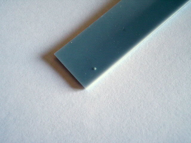
Figure 12. Hole Effect on Bottom of Printed Part
Interestingly I think there is another effect occurring with the very thin layers. These are optically transparent and I suspect that as a consequence they are subject to greater resin shrinkage during post-wash cure.
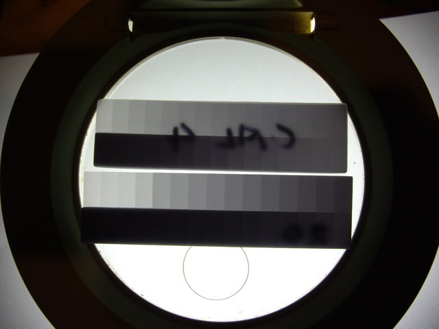
Figure 13. Optical Transmission through Calibration Prints
(Upper is prior to axial play modification. Lower is where I’m at today.)
After further resin-specific slicer parameter refinements I’m now consistently achieving individual layer and cumulative Z heights within 0.05 mm (2,000th of an inch) of the STL model printing directly off the build plate. This is well within typical non-specified machining production tolerance of 0.127 mm (5 thou) and should be good for most models. I expect that I am now approaching the limits of what is achievable on the Elegoo Saturn 2.
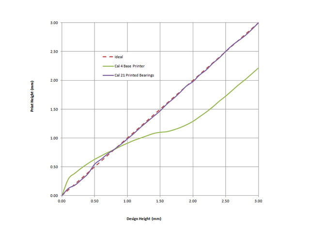
Figure 14. Almost Perfect Print Height Directly off the Build Plate
Click on Gear Pump to link to another page on the Saturn 2.
|