|
The design started by measuring the fans, existing bracket, dial indicator gauge mount and associated clearances to other stuff. While the design needs to be secure it should not add significant weight to the mounting – If necessary I will dispense with the existing fan cowlings to reduce weight (probably a good idea in any case because they are only there to stop you sticking you finger in the fan and they restrict the air flow area).
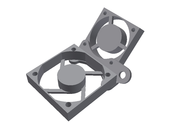
Figure 1. New Fan Bracket and Dial Indicator Gauge Mount
Design Concept
Here is the concept showing the mounted fans and the dial indicator gauge mount. The model was drawn in AutoCad Inventor, exported as a .STL file, and converted to gcode using Simplify3D. The only hassle I had was the requirement to rotate the model in Inventor to get what I figured would be the optimum orientation in Simplify3D for printing. This is a simple part but it has oblique angles to the print bed with no user specified supports. I will not be disappointed if the printed part is a disaster.
I built the gcode for the M2 V3B extruder (0.35 mm extruder nozzle) defaults for PLA with 30% infill precision print and added a raft.
I powered on the M2, connected to my laptop, and started my first real print.
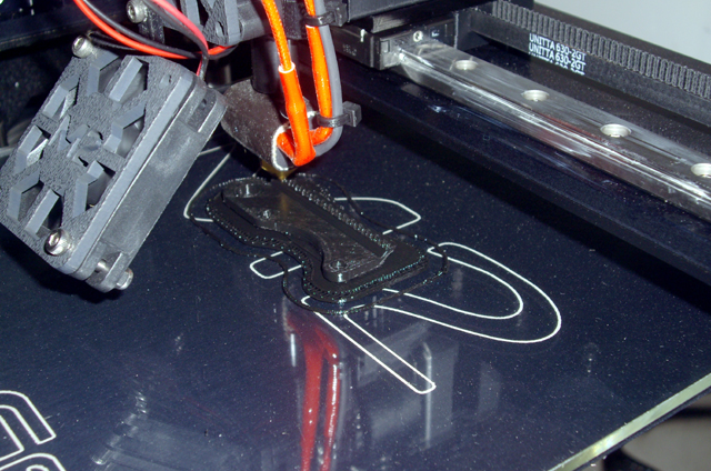
Figure 2. First Real Print in Progress
The results on the print bed looked fantastic. I had some problems separating the raft from the print bed which required the use of a razor blade (taking care not to scratch the borosilicate glass plate). When I separated the raft from the part, the base of the part was pretty rough – it would have been much better without the raft (the base of the raft was glossy smooth). I decided to sand the flat mating surfaces which revealed some layer adhesion problems around the 50 mm fan mounting holes. I suspect that this is due to a lack of supporting structure and the proximity of the fan mounting holes to the edge of the part. I cleared all of the holes with an appropriately sized twist drill rotated and fed by hand.
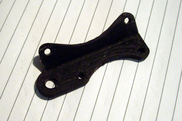
Figure 3. My First Part
The only problem of any consequence is that I got the 50 mm fan mounting hole separation wrong by 2 mm. This was readily corrected with a round needle file. I have subsequently corrected the model but my first print is good enough for use and I have fitted it to the M2. The fan mount is much improved.
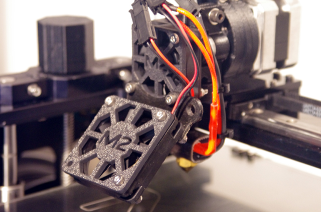
Figure 4. New Bracket Fitted
The dial indicator mount works beautifully, but it does not provide full coverage of the heated bed in the -X direction and, on reflection, there is a problem with this method. My first test measurements with the dial indicator gauge indicated that the glass plate was not flat with a hump in the centre. Glass plate is actually pretty flat provided it is not subject to tensional or torsional forces so something else is causing this measurement anomaly.
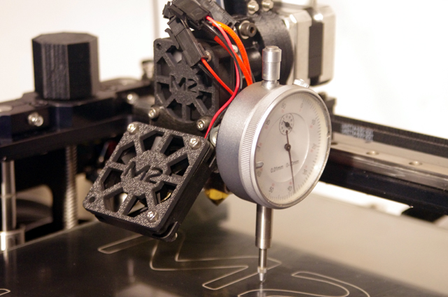
Figure 5. Dial Indicator Gauge Mount.
The small force (around 1 Newton or about 100 gm) required to operate a dial indicator gauge plunger causes the bed to deflect downward every so slightly on the bed springs. This force is not constant over the bed depending on the compression of individual springs and the distance the measuring point is from them. So the dial indicator gauge will change the dimensions that you are trying to measure.
I will revert to using feeler gauges for levelling the bed in future until I can figure out a non-bed contact measurement method.
If you have any questions, comments or suggestions please email me. I will respond. Otherwise click here to navigate to Heated Bed Platform (HBP) cable loom support...
|