|
I was printing a part for Dremel press to convert it into an elecrode holder for welding battery tabs. This is is quite a big print job. The first print failed through what appeared to be inadequate support structures (but in hindsight it was probably an extruder issue).
I adjusted the model’s support in Simplify 3D and started the print again but it failed after a couple of hours due to a communications error on the USB between the driving computer and the M2. This is not the first communication error that that I have ever experienced and I suspect that the problem is the USB port in the driving computer. I cleaned all of the USB connectors with isopropyl alcohol, tightened the male cable to computer connector by bending the case ever so slightly, and made sure that all of the plugs and sockets in the M2 electronics were clean and positively seated.
I started the print for the third time and I could hear occasional extruder slippage. This is an intermittent clunk sound on top of the singing X and Y drives. With the print over half completed the extruder blocked solid and another partial print was destined for recycling.
The extruder nozzle was cleaned quite recently (within the last 20 print hours) so it was time to pull the extruder to bits and find out what was going on. First up there was a lot of white dust in the extruder path. This is gypsum plaster dust from recent renovations even though the M2 is placed under a plastic bag when it is sitting idle. The extruder housing is open for cooling so I figure the dust had simply been blown in by the cooling fan.
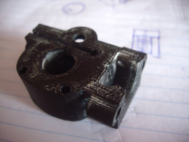
Figure 1. White Plaster Dust in Extruder Housing
The extruder idler bearing seems to be locked and is far from clean. The idler adjustment is right at the upper limit of its range so I figure that the clearance between the idler bearing and the toothed filament drive pinion is way too tight. The toothed filament drive pinion looks to be in good order.
The 3D printer extruder path was cleared, cleaned and re-assembled. The most significant issue that I found was that the brass extruder barrel was not properly seated in the plastic drive fitting. The gap had filled with PLA forming a solid plug at the top of the barrel. This probably happened during the last nozzle clean. When the plug forms and solidifies it prevents filament extraction and impedes filament drive. I had to carefully drill the recess clear with a 1.6 mm diameter twist drill. There was a significant ring of hard carbon in the extruder barrel that which had to be scraped off using the blunt end of the 1.6 mm drill bit followed by polishing using a piece of string soaked in metal polish. My technique for cleaning the extruder nozzle worked just fine.
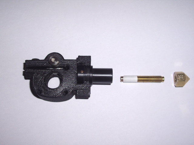
Figure 2. Extruder Cleaned and Ready for Assembly
(Left to right: housing, plastic housing adaptor, brass barrel and nozzle.
The aluminium heater block is not shown.)
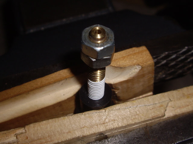
Figure 3. Assembly of Barrel into Plastic Adaptor.
(Note soft wood to protect plastic adaptor and lock nuts for tightening the barrel.)
With the printer re-assembled it was time for another attempt at the print. The part seemed to be printing okay but there is still a strange intermittent ticking noise from the extruder. Something still isn’t quite right. About half way through the print the extruder failed again.
This is becoming tiring. I have a spare factory-assembled hot end so I fitted this and started another print. The ticking noise hadn’t gone away. Something else is clearly amiss. Towards the end of the print the extruder started to slip intermittently (the dreaded clunking noise) and then stopped extruding.
I removed the hot end and fans from the extruder motor and drove the motor while holding the drive gear. The planetary gearbox is clearly stuffed. Under moderate load it skips making the clicking noise. I can see that the motor shaft is still turning at the back of the motor. I stripped down the gearbox. There were loose metal particles in the grease and I figure that the motor pinion gear has been partially stripped as this is the weakest link in the drive train. On cleaning and inspection this proved to be correct. The remaining planetary gears (ring and three idlers) were in perfect order.
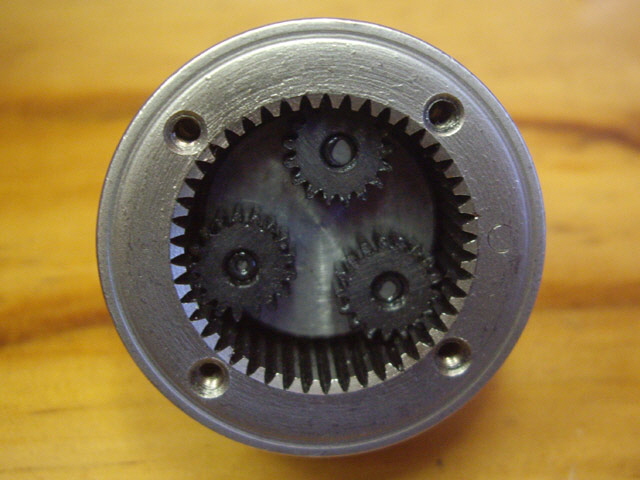
Figure 4. Planetary Gears in Good Order
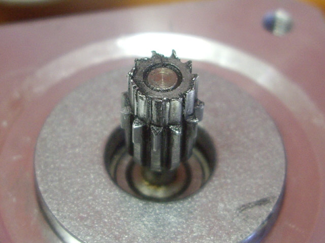
Figure 5. Motor Pinion Gear Stripped
All is not lost. I have recently received a brand new extruder motor from MakerGear for my dual extruder upgrade. I fitted the new motor with the new hot end and the clicking noise vanished. I immediately placed a new extruder motor complete with gear box on order (for my dual extruder) and a new motor pinion so I can restore the old extruder motor.
While the fault has been identified and repaired it is worth while thinking about the cause. If the extruder nozzle or barrel blocks due to an obstruction then ideally the filament would simply be stripped between the idler bearing and the toothed filament drive gear. However if the clearance between these is not set properly then the filament won’t strip and the drive torque will cause the motor pinion gear to wear and eventually strip. So while the immediate cause was probably the dust (which caused the extruder nozzle blockage) the root cause was likely incorrect setting of the extruder drive idler bearing when the M2 was first assembled. There are no instructions in the three M2 assembly guides for setting the extruder tension and I don’t recall ever setting it. Hence I probably fitted the extruder head with the filament drive compression far too tight. Click here for instructions on correctly setting the extruder compression.
- Avoid operating the printer in a dusty environment. This is likely to result in an extruder nozzle blockage.
- When cleaning and lubricating the printer (after about every ten hours of printing) check for an accumulation of dust on the extruder cooling fan. If it is dusty then strip and clean the extrusion path.
- Adjust the extruder drive filament tension with every change of filament. The appropriate setting provides between 10 to 15% compression of the filament with no distortion in the filament’s circular cross section.
I figure that the original hot end is still serviceable. I’ve re-cleaned it, re-seated the barrel into the plastic adapter and placed it in my increasing M2 spare parts set.
Replacing an Extruder Pinion Gear
A replacement pinion gear has arrived. Fitting is relatively straight forward and takes about an hour including cleaning.
Remove the gear box from the stepper motor (four machine screws). Pull the motor free from the gear box (no force should be required). Strip the gear box and clean off all of the old grease.
A gear puller should be used to remove the old pinion gear from the motor shaft but chances are that you won’t have one, or if you do it will be too big. So support the motor in a vice with the pinion gear facing up. Using two large flat bladed screwdrivers gently lever on opposite diagonals (by the mounting bolt holes where the motor casing is thickest) between the motor housing and the underside of the pinion gear. Apply equal pressure on each side. The pinion gear should slide off the motor shaft. If it refuses to move then you may need to heat the pinion gear enough to release any adhesive and expand it slightly. A soldering iron should be an adequate heat source.
Clean the stepper motor shaft and the new pinion gear. The shaft is 3.00 +/- 0.05 mm in diameter and the shaft hole of my new pinion gear is 3.10 +/- 0.05 mm diameter. This is a free running fit so the pinion gear must be adhered to the shaft. With the pinion gear boss towards the motor fit the pinion gear onto the shaft and align the end of the shaft with the the top of the pinion gear. Apply a single drop of super glue to the top of the shaft. It will migrate into the gap by capillary action and set within a few seconds. Wipe any excess glue off the top of the shaft.
Reassemble the gear box (including the end washer) and apply a liberal dollop of molybdenum grease to the idler gears. Clean off any excess grease from the motor recess. Now gently fit the motor to the gear box (no force required) turning the gear box shaft slowly by hand until the gears engage and the motor sits flush with the gear box. Refit the four motor mounting machine screws.
Finally, gently turn the gearbox shaft. The motor should turn smoothly and freely with a low pitched whistling sound. If there is any binding then either the idler gears or ring gear are damaged or there is tramp metal still in the gear box. These will require the gearbox to be stripped down, cleaned and inspected before attending to the problem and reassembly.
Click here to navigate to X, Y and Z calibration...
|