|
The OEM build of the wiring in the control cabinet is poor. Errors include unsafe earthing, incorrect phasing, loose terminations, inefficient layout and excessive (unnecessary) wiring. To complicate matters there was no schematic and the wires are not colour coded (everything is black or red and sometimes black turns to red, and visa versa, at terminations. Expect to spend several days putting this right. Read on to understand the issues in more detail.
Time to apply some power!
But before I can power up the machine I need to check mains earth continuity. We have a problem. No earth connection! Opening the control cabinet the problem was immediately apparent. Earth is switched along with neutral and phase on the main rotary power switch. This isn’t good practice. The mains cable earth wire should terminate on a dedicated earth stud connected to the chassis. I set about fixing this. We now have a solid dedicated hard-wired earth for the machine. I have added an Earth tag to the exterior of the machine. The purpose of this tag is to ensure that the earthing stud stud is not inadvertently removed during future service by other folk. Note that in the OEM build the sub-frame was earthed, but the sub-frame was not securely bolted to the control cabinet. This was remedied.
You will see in the images below that the conduit covers have been roughly hacked off with side cutters. It would have taken WMT about 30 seconds to square these and remove the sharp edges with a file.
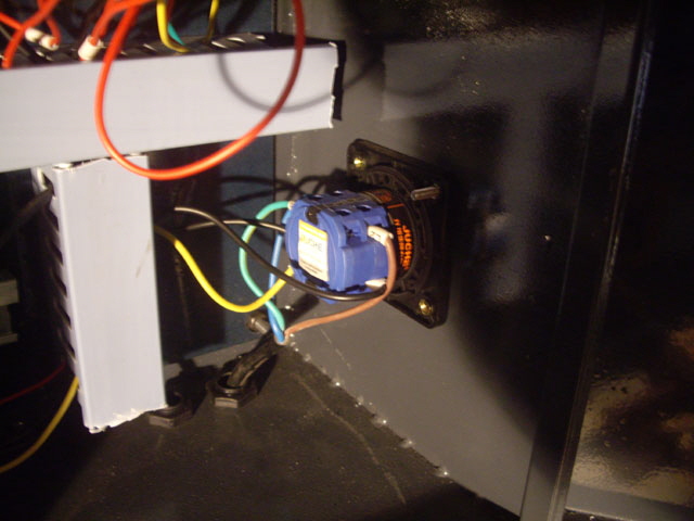
Figure 1. Switched Earth - BAD
(Note the poorly cut ends on the conduit covers.)
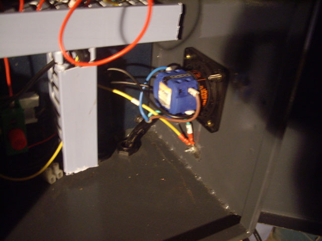
Figure 2. Dedicated Hard Wired Earth Stud
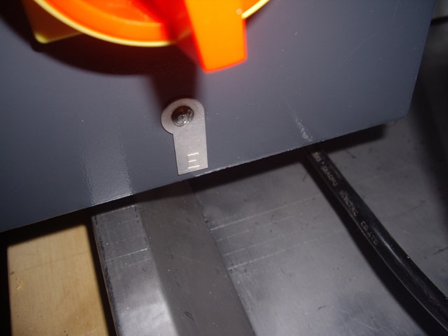
Figure 3. Earth Stud Label on Exterior
(Main power switch above.)
With the machine connected to the mains via an Residual Current Device (RCD) I turned on the main power switch on the left hand side of the control cabinet and re-set the emergency stop (on top of the control cabinet ) by twisting it clockwise. Note that none of the controls are labeled and there is no diagram in the manual. The start push button illuminates (but I don’t think it should) and nothing else is happening?
On opening the control cabinet the problem is that the neutral lead has come adrift from the main power switch. While it probably dislodged when I removed the switch for making the earth stud it can’t have been secured properly. A question you might ask is, ‘With neutral disconnected how did the push button light?’ The push button LED return path is probably to Earth either through the secondary of the main power transformer (which is probably earthed) or due to a phase neutral reversal in the wiring. The current from the LED (or lamp) is too low (below 30 mA) to trip the RCD.
With neutral reconnected and power power reapplied I can hear the contactors pull in when I press start. The machine is humming quietly due to the cooling fan on the spindle motor frequency controller - its LED display shows ‘00’ and flashes ‘H’ with an Hz status LED (I have no idea what this actually means but I figure it is telling me that the output frequency is zero). The is also a green status LED glowing below the main breakers. The machine won’t be doing anything until the control computer is attached via the USB port, but this will have to wait until tomorrow.
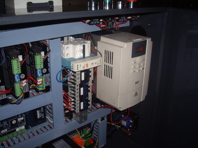
Figure 4. Power Successfully Applied at Last
Modifications
In messing about with the control cabinet wiring I noticed the lack of a mains filter and the relatively small filter capacitor on the main DC supply (just 2,200 uF). The capacitor is fixed by cable ties to the transformer output wiring and, while relatively secure, this is not ideal. Under normal CNC operations there will be a lot of relatively high current switching going on. A mains filter will reduce susceptibility to mains noise but more importantly it will also reduce noise being coupled back to the mains from the machine. A larger filter capacitor will certainly reduce ripple on the DC supply. I have a 10,000 uF 100 V capacitor kicking around somewhere and I’ve ordered a 10 A filter block (about $30). I’ll be fitting these tomorrow.
Making the holes for remounting the heat sink with the machine on the bench was a bit of a challenge. I didn’t want to damage anything and there is no room to get a drill into some of these spaces. So all other holes were drilled with a Dremel flexible drive.
Note: the control cabinet electrical and electronic wiring is on a separate steel base plate from the cabinet proper. I suspect that the intention of this arrangement is to allow external assembly of the control cabinet. The base plate attaches to the cabinet through four M10 studs at the corners. The plate was loose and my first thought was that it was mounted on springs to protect the electronics from machine vibration. Eventually (during rewiring) I found that there are no springs - the stud nuts just haven’t been secured. Ideally the base plate should be on ~10 mm standoffs to allow protrusion of bolts used for mounting the components.
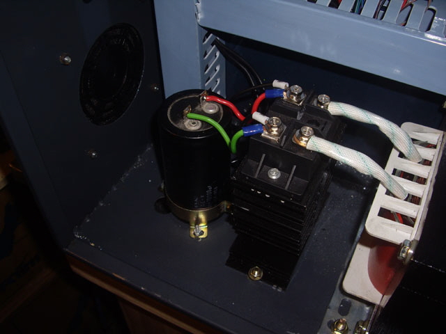
Figure 5. 10,000 uF 100 V low ESR Main DC Filter Capacitor
(Replacing 2,200 uF OEM capacitor)
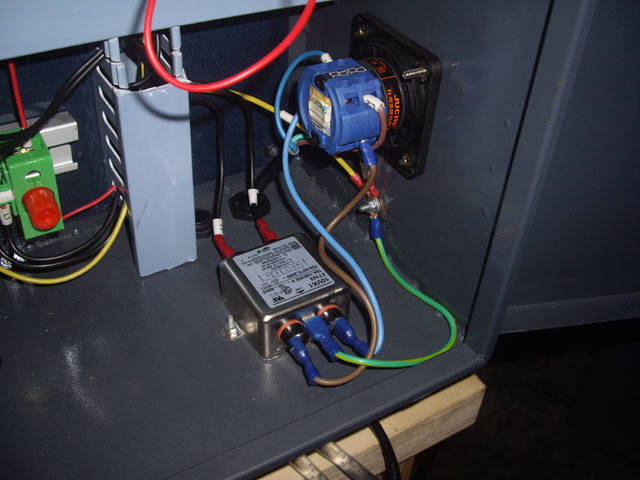
Figure 6. 10 Amp EMI Filter Block
The EMI filter is really just a nice-to-have but, interestingly, fitting it has fixed the illumination of the power on push button discussed above. The power on lamp now only lights when it is pressed. I can’t find the Schneider Electric part number for the illuminated Normally Open push button head but I suspect that the LED has a return path is ground. Phase and neutral reversal will result in the LED always being on. This is another issue that should have been identified and resolved by WMT.
In completing these modifications the main bridge rectifier heat sink literally fell off its single mounting bolt. The bolt is the wrong size, there should be at least two, and the bolt hole is also the wrong size. This isn’t good workmanship or Quality Assurance WMT. I’ll be remaking the heat sink mount tomorrow.
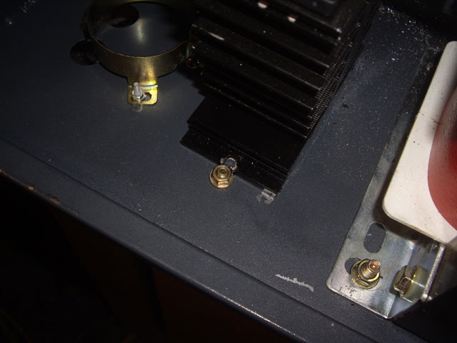
Figure 7. Poor Bridge Rectifier Heat Sink Mounting
Today I tidied up all of the poor machining on the bridge rectifier heat sink, remounted it to the case securely with two M3 machine screws into threaded holes on the base, added some more heat sink paste because the original application didn’t provide good coverage, and remounted the bridge rectifier. It is now secure.
I’m about to make some more changes to the XK7113D wiring to incorporate a misting cutting fluid system (of my own design) and couple the spindle motor cooling to the motor drive. These changes are essential for the cutting fluid and protection and longevity of the spindle motor and will simplify Mach3 code, and actually reduce the number of modules in the control cabinet.
Before I actually make the changes I need a schematic diagram of the wiring so I can revert to original. WMT won’t provide a schematic (this is not great support and in my opinion and a schematic should be incorporated in the users manual) so I need to trace the wiring. This means removing the cable conduit covers and physically tracking and recording the route of each cable and wire. The wiring is almost all red or black, occasionally with red connected to black. While the majority of the cables have sleeve labels these are often hard to see. The wiring could be improved with colour coded insulation.
The tracking exercise took an entire day, but now I have enough information to be getting on with the modifications. In the tracking process I found three loose terminations. These are manufacturing faults and I’m pleased to have found them before they caused a fire (loose terminations tend to get hot over time) or a fault. In fact one of these terminations is likely to be responsible for the spindle motor cooling relay chatter that I experienced some time back and an intermittent issue with the Z axis brake.
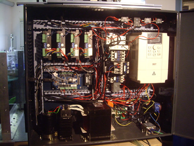
Figure 8. Tracing the Wiring
(A challenge because every power cable is either black or red).
While the OEM wiring looked nice and tidy concealed in the conduit, it is far from optimum. WMT could reduce conductor lengths (and cost) by design optimization and repositioning some of the modules.
My draft schematic of the power routing in the XK7113D is shown in the following figure. It is not quite complete (the controller board, stepper motor drivers and spindle motor are not shown) and it is still in draft because I can’t get at some of the terminations. The schematic is not optimized for function or minimum wiring because I have tried to show the actual wiring to aid future servicing. The schematic incorporates the modifications that I have already carried out (earthing, main power switch, phase/neutral reversal and EMI filter).
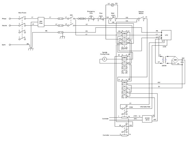
Figure 9. Draft Power Side OEM Schematic
The next stage is to incorporate the changes to the spindle motor cooling pump circuit and incorporate the drive for the cutting fluid pump. I will be replacing the existing relays with 10A 240VAC/24VDC types, incorporating a new relay for the cutting fluid pump, removing the spindle motor cooling pump contactor, and replacing the existing DC/DC converter with a unit rated at 10 A to drive the cutting fluid pump.
The cutting fluid pump relay will be driven by the VFD RUN FORWARD signal from the controller as opposed to one of the spare relay outputs in the VFD.
Here is the modified (and somewhat simplified) schematic. In addition to the changes proposed above, phase and neutral are now both switched through the main contactor. Note that the control switches and pilot light have axillary protection through a 2 A cartridge fuse as recommended by Schneider Electric.
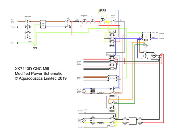
Figure 10. Modified Schematic for Cutting Fluid Pump
The new wiring will be colour coded. The OEM build has every power cable either black or red, and on at least five occasions transitions from black to red. While most of the wires are fitted with label sleeves these are a complete pain to read, particularly when they are jammed under a termination with the inscription not visible. Interestingly they are also an added cost. WMT would do well to use coloured insulation in future builds.
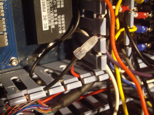
Figure 11. Black to Red Transition.
(Note: I’m midway through rewiring - hence multi-coloured insulation.)
Okay, on with the rewiring. I’m using 1 sq mm PVC stranded copper wire (about AWG 18) with a current rating of 15 A. All terminations are with insulated termination crimped spade connectors, all made using a real crimping tool. You cannot make an effective crimp connection with pliers and using a real crimping tool makes for fast, consistent and sound terminations.
The rewiring is progressing steadily, but I was interested to note that the illumination module, Schneider ZB2-BWB..C, for the start switch was labeled as ~24 (that’s just 24 VAC). The module was powered in the OEM wiring across the 240 VAC supply. I’ve triple checked this, and in any case there is no 24 VAC supply available in the control cabinet.
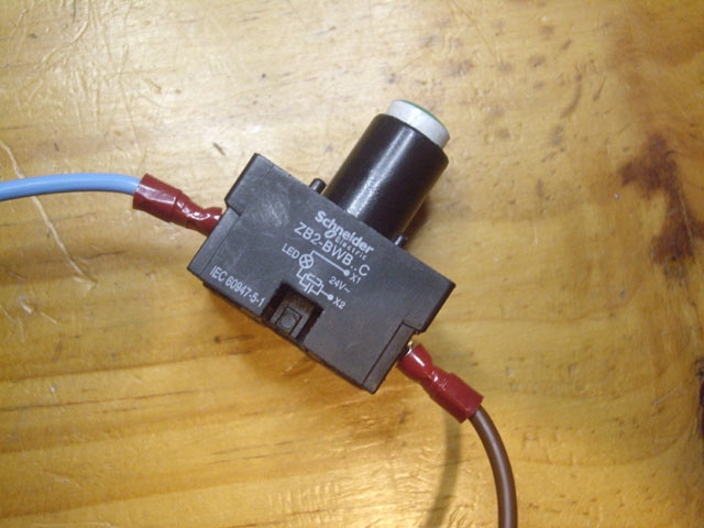
Figure 12. Pilot LED for Start Switch
Finding the Schneider data sheet for the normally open push button switch illumination module was a bridge too far. The reason is that the XB2 range is now obsolete (replaced with the XB4). While replacement XB4 units are available that are functionally equivalent, the modules aren’t. I don’t want to buy a new switch if I can avoid it because they are expensive (say NZ$50 to $100 depending on the model).
So I tested the illumination module on a DC 24 Volt supply. It illuminates just fine with either polarity but it is only drawing 0.28 mA. This seems inordinately low (yes, I double checked the measurement). Current measurements from two further tests at 20 and 40 VAC 50 Hz were 0.27 and 0.58 mA.
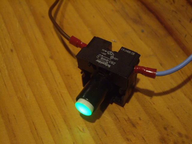
Figure 13. Pilot LED Glowing Brightly Drawing Just 0.28 mA from 24 VDC
So the LED module appears to be passive resistive at about 86K Ohms, and probably in series with two LEDs connected in reverse parallel. At 240 VAC we can expect that the current will increase to about 2.7 mA. At this projected current the unit will be dissipating about 0.5 W, primarily in the resistor. These measurements are somewhat below the Protected LED ratings for similar Schneider illumination blocks. So I figure that the illumination module is not labeled correctly (it should be ~240). And it should not get unduly hot or explode when operated across 240 VAC mains.
With this issue resolved (I can re-install the OEM pilot LED module) I can be getting on with the rewiring.
The 2 A slow blow fuse used to protect the switches uses a different mounting rail from the circuit breaker and contactors, and is mounted about 450 mm below the switches which are at the top of the control cabinet. I’ve made a new extended mounting rail and moved the fuse to the top of the control cabinet; saving about 1 m of wiring and placing the protective device beside components it protects.
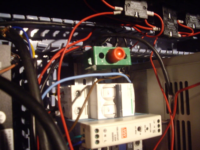
Figure 14. Repositioned Cartridge Fuse on Extended Mounting Rail
The control cabinet contains a 24 VDC module that connects to the Z axis brake. I can’t find any information about the module or the brake but, based on the module labels, the phasing is incorrect, it is activated through switched neutral, and there is no protective earth. The 24 VDC wiring to the brake is shielded, but the shield termination is floating and uninsulated. I’ll be attending to these issues.
While doing the rewiring I found that the sub chassis was not bolted down to the control cabinet. My earlier thoughts on why it wasn’t secure was that it was spring loaded to absorb machine vibration, but this was wrong. I have tightened the stud nuts and now it is secure.
Due to interruptions, time out to research thing like the pilot light voltage, having to make mounting rails, and keeping the schematic updated, the rewiring took also almost two days. Before I reapply power I have a few more Ohmmeter checks to complete but everything is tidy, secure, almost optimized, and colour coded in accordance with the schematic above. The amount of wire in the conduits has been reduced significantly and the conduit covers snap easily into place.
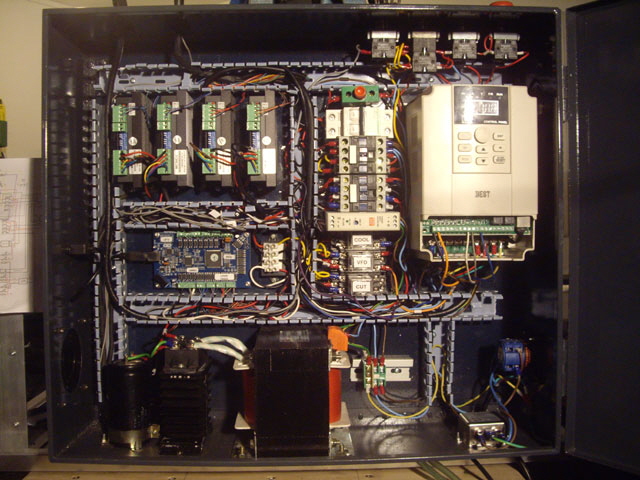
Figure 15. Almost Done
The job isn’t quite finished because I’m still awaiting arrival of my new cutting fluid pump and the 10 A 48 VDC to 12 VDC converter (necessary to drive the 12 VDC 5 A pump). I’ve made appropriate allowances for replacing the existing DC/DC converter so fitting the pump should be straight forward.
I’m going to be removing the termination block and rail to the right of the main transformer for mounting the new DC/DC converter. The terminal block is very poorly constructed and is on the verge of falling apart all by itself. With the cabinet securely earthed through a dedicated bolt and the sub frame secure, the block serves no useful purpose. In fact it ruins a single point (star) Earth connection which is an effective way of preventing ground loops and associated noise.
The new DC/DC 48 V to 12 V 10 A modules (I ordered a spare) arrived today so I’ve installed one, replacing the exiting DC/DC module. It bolts straight to the sub-chassis to the right of the transformer where the old terminal block (removed) used to reside. Well not quite. First you need to separate the sub-chassis from the cabinet, mark out, drill and tap the holes (M4 x 0.7), and finally re-secure the sub-chassis to the cabinet. Oh, and best we clean up the swarf.
There were a few other tidy up jobs required:
shortening a few lead lengths and straightening out the wiring in the conduits,
moving the EMI filter to the side wall above the main power switch,
fitting two new screw terminal blocks (one for the DC/DC converter and one for two pump motors) with Perspex base plates, and
moving the main power and pump motor cable glands to the back of the control cabinet (below the door hinges).
The Perspex base plates for the screw terminal blocks are not actually required but they do reduce the possibility of an inadvertent chassis short through pulled cables, and prevent cable wear against the chassis due to machine vibration. The base plates also allow for fitting of base mounted fuses which are on order. I’ll need to incorporate these in the schematic too.
Unfortunately I couldn’t avoid the colour coding mismatch on the DC/DC converter without buying another reel of 1 sq mm cable in a different colour or fitting sleeves over the converter wires. Almost all of my heat shrink is the wrong diameter or colour for this simple task. I may revisit this, but at least the mismatch is not hidden in the conduit.
An issue with the original design is that you need to remove the conduit covers and mess about with the wiring in order to disconnect the spindle pump motor. Removal (or either pump motor) is now very straight forward and the cables hang clear of the table and tray without a nasty kink. When the cutting fluid pump arrives this should route straight through the cable gland and terminate directly at the adjacent terminal block. Another option was to fit IP67 screw locking chassis sockets but I don’t have any on hand that are rated for 240 VAC or 10 A DC, and in any case they are rather expensive.
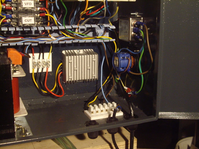
FIgure 16. New 10 A DC/DC Converter, Quick Disconnect Pump Terminal Block, and
Relocated Cable Glands.
(Note the unavoidable colour coding mismatch)
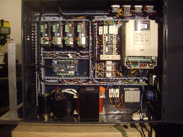
Figure 17. Rewiring Complete
I’ve still got a few Ohmmeter tests to complete but aside from fitting the new fuses; the cutting fluid pump; testing, adjusting, and mounting the misting nozzle; and re-bolting the mill down to the table we are almost back in business!
As an aside, the clearances around the VFD are significantly less than the VFD manual recommends for effective cooling. There isn’t much I can do about this other than add a fan to the control cabinet if the VFD starts running hot.
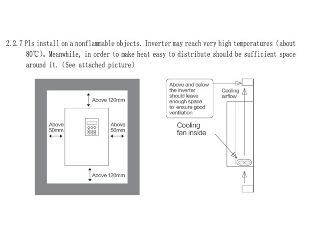
Figure 18. VFD Clearance for Cooling
The Ohmmeter tests are complete. No errors found and everything is correctly and securely connected. In cleaning up I was interested to see how much wire I had removed from the original install (even though the new circuit is slightly more complicated than the OEM install). About 8 m of new wire went into the loom, and a lot of the old wire was reused. But this still left me with just over 18 m of remnants on the shop floor. So rewiring has removed about 10 m of wire.
I’m still waiting on delivery of my new base mount 6.35 x 25 cartridge fuse holders. In the interim I need to get the mill bolted down so I can complete functional testing with power applied.
A Minor Setback
I hate writing up my personal failures but sometimes I get stuff wrong and if I were reading this page then I’d like to know what actually happened, and not the sanitized version. I set about the energized testing today...
Mach3 up and running on the control computer (all good). Main power switch on (all good). Start button pressed. The start light illuminated, both contactors kicked in, and unexpectedly two of the relays also actuated causing the spindle cooling pump to start. Within seconds there was a heap of acrid white smoke from the control cabinet. Power off and mains disconnected!
The new DC/DC converter has fused (actually the case has aluminium case has split and it may have actually caught fire). Interestingly the main breaker, an external RCD, and the switch board fuse did not clear the fault.
The cause is a silly mistake (my dumb). I have inadvertently wired the output (12 V) to the input (48 V). Bugger! Unfortunately the module has the wiring connection label on the underside so it cannot been seen when the module is actually mounted, and the colour coding is different from the OEM DC/DC converter.
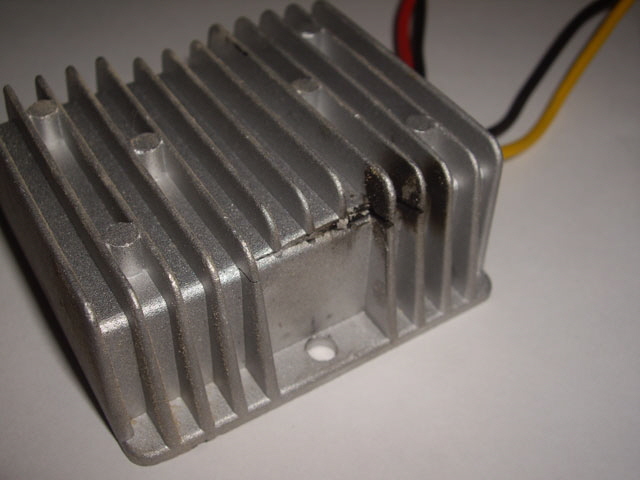
Figure 19. Fused DC/DC Converter
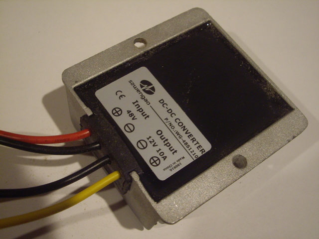
Figure 20. Connection Details on Underside - and Different from OEM Device
The converter is toast and I may have damaged one of the opto-isolated El 852 Darlington drivers on the control board. The relays are still completely serviceable despite a brief over-voltage on the coils. There is some charring and soot on the conduit immediately above the DC/DC converter and the insulation on two wires has been burnt by heat from the DC/DC converter.
What I was expecting was a progressive power up, allowing me to check stuff one step at a time, but the VFD X1 ‘start-forward’ relay appears to have energized immediately from the controller board on power up, causing the spindle motor cooling relay to energize.
I have replaced the damaged wiring and installed my spare DC/DC converter (with the wiring correct this time). The relays have been tested and they’re all good. The conduit and all surfaces in the control cabinet have been wiped down.
It is possible that the 0-1 EL 852 opto-isolator on the controller board has also been damaged depending on the on the sequencing of the DC/DC converter failure. The reason for this potential failure is not the voltage (the opto-isolators are rated at an open circuit voltage of 350 V) but possible excessive relay coil current and power dissipation. The EL 852 is rated for 150 mA maximum collector current and a power dissipation of 320 mW. The relay coils have a resistance of about 150 Ohms. So from 12 V they draw about 80 mA, but from 48 V they’ll draw close to 300 mA. The power dissipation in the Darlington drive transistor (assumed saturated) under these circumstances would have been about 360 mW.
EL 852 opto-isolators are through-hole components so replacement should be straight forward (should this be necessary). I have some spares on order. Interestingly this component is not recommended for new designs.
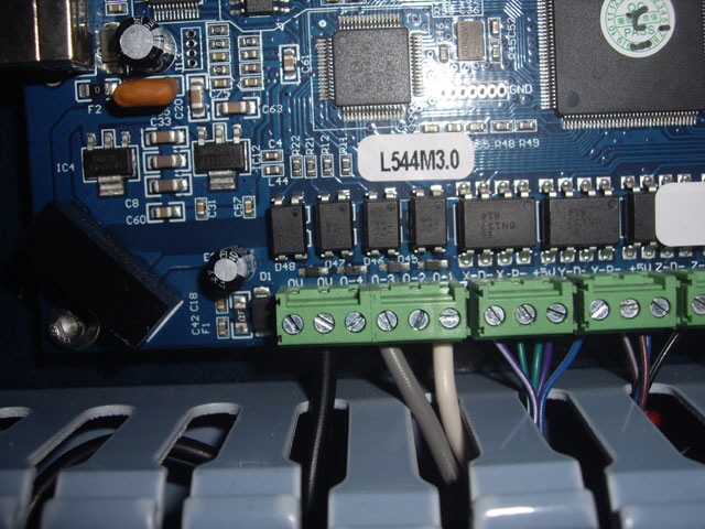
Figure 21. The Four Opto-Isolated Drivers on Controller Board
However the DC/DC converter did get very hot very quickly and I’m rather hoping that this caused both the 48 V supply to pull down under the load, and early failure of the as-wired output to ground. In the failed condition the resistance between the 12 V terminations (inadvertently connected to the 48 V rail) was just 5 Ohms, and the 48 V terminations (inadvertently connected as the 12 V output) have a resistance of about 30 K Ohms to both ground and the input. Under the failed condition the relay coil current would have been just a few milliamps, so the EL 852 opto-isolator on the control board may have survived. I have placed some spares on order just in case, but if necessary I can move one of the two unused opto-isolators on the controller board.
The power of sequencing of the VFD X1 (Run Forward) control is a problem. If the controller board initiates this signal on power up then, with the current wiring, the spindle cooler pump will start every time the mill is started, but it only needs to run when the spindle motor is actually driven. The Y2A and B normally open output relay on the VFD can be configured using Parameter P102 = 1 for actuation on running. The current default setting (P102 =4) is for actuation on fault. It is not clear if ‘running’ means that the spindle motor is actually being driven, or if the device is powered up. I will need to take some measurements.
Interestingly, the controller card manual shows a direct connection between the 0-1 opto-isolator output and the VFD X1 input. Both the OEM wiring and my revision have the VFD X1 input actuated through a relay. Maybe this relay isn’t required?
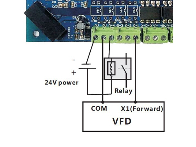
Figure 22. Controller Card Manual on VFD X1 Drive
The VFD manual states:
2.4.5 The control loop wiring
1) “COM” terminal is control signal common terminal, do not public grounded.
2) The wiring of control circuit terminals should use shielded or twisted pair, and must be wired separately from main circuit and strong electrical circuit.
3) Since the frequency input signals of control circuit are micro current, in the occasion of contact input, in order to prevent poor contact, please use the two side contacts or twin contacts.
4) Control loop is recommended 0.75 mm2 cable wiring.
5) High voltage can not enter into control loop , otherwise it will damage the inverter.
There are two internally connected COM terminations on the VDF control loop terminal block, both of which are connected to the controller card. One is used as the return path for the 10V power supply to the controller card. The other is the return line for the four opto-isolator outputs on the controller card.
There are three 0V internally connected 0V terminations on the controller card which is powered from the 10V and COM terminations on the VFD.
The common negative terminal on the 12 V and 48 V DC supplies is not connected to mains earth.
I can’t estimate the current for the controller card. It has a Spartan 6 FPGA and could be over an Amp, so the power supply connections from the VFD to the controller card need to be in the range of 18 to 20 AWG (say 0.8 to 1 mm diameter). I’ll leave these as they are. But a relay coil current is ~ 80 mA so AWG 26 rated at ~ 1 A is fine for the other connections between the controller card, the VFD and the relays. The existing wiring doesn’t use twisted pairs of shielded cable for these connectors so I won’t be either unless noise becomes a problem.
There is no requirement to connect all of the COM and 0V terminations between the controller card and the VFD provided that there is at least one connection between COM and 0V, and one connection from either COM or 0 V to the 12 V DC negative supply.
As a result of this analysis I have further modified (and simplified) the schematic, getting rid of another relay in the process and actually removing some more wire.
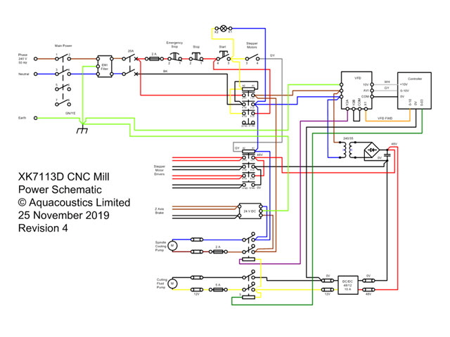
Figure 23. Revised Schematic
I have modified the wiring to the new schematic, stuck a copy to the inside of the control cabinet door, and I’m ready to begin testing all over again, starting with continuity tests with an Ohmmeter. Everything tests okay and this time I was able to progressively power up and test stuff.
Control computer on. Mach3 running and USB connected. Confirm USB LED on controller board. All good.
XK7113D Main power switch off. Stepper motor switch off. Power applied through an RCD. All good.
Start push button tested with main power switch off. Nothing happens as expected. All good.
Main power switch on. Nothing happens as expected. All good.
Start push button. Main contactor operates. Pilot light is lit and latched. VFD shows H 00.0. Braking 24 supply shows DC LED. No relays active. 48 V DC is active. DC/DC converter has 12.3 V output. All good.
Stop push button. Main contactor releases. Pilot light off. DC rails discharge. 24 Volt braking supply off. All good.
Start push button (again). All good as above.
Stepper motor switch on. Contactor operates. Stepper motor driver modules show green LEDs. All good.
Stepper motor switch off. Contactor releases. No 48 V DC to stepper motor driver modules. All good.
Stepper motor switch on (again). All good as above.
Reprogram VFD parameter P102 from 4 (default) to 1 for operation of spindle motor cooling pump. All good.
Through Mach3:
Exercise X, Y, Z and home zero. All good.
Turn on spindle motor at 1,000 RPM. Spindle motor starts. Spindle motor cooling pump relay actuates and pump starts. Increase to 2,000 RPM.
Spindle motor off. Pump stops. All good.
Flood cooling on. Relay operates. 12 VDC applied to cutting fluid pump terminations (no motor connected as yet). All good.
Flood cooling off. Relay releases. All good.
Stop button pressed, main power switch off, disconnect from main. Control computer off.
Everything is now working as expected. The spindle motor cooling pump now turns on and off with the spindle motor. This ensures that the spindle motor will always be water cooled. This also frees up the gcode M3 command for operating the misting pump as is intended from Mach3. The pump drive works just fine but I have some more work to do with the misting nozzle (it only does flood cooling at the moment).
The 0-01 opto-isolated drive on the controller board is serviceable so I don’t need to replace it. I now have some spare components in stock in case of a future disaster.
So apart from installing the two cartridge fuses on the pump motor output terminals the rewiring is complete. The exercise has resulted in:
- tight wire terminations on all components and modules,
- simplified colour coded wiring (removing about 10 m of wire from the loom),
- removal of a contactor and a terminal block (I now have a spare contactor),
- improved relay ratings (now 230 VAC, 20 VDC at 10 A),
- improved spindle motor cooling pump sequencing,
- improved external pump circuit protect (once the cartridge fuse holders are fitted),
- more appropriate cable gland positioning with terminal blocks for easy connection and removal of the external pumps, and
- a 12 VDC 10 A supply for operating the cutting fluid pump.
The fuse holders have arrived and are now installed. Note that the screw terminal blocks that I am using are rated at 400 V AC 10 A.
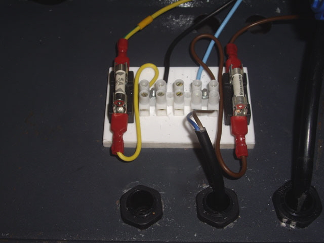
Figure 24. Fuses Installed on External Pump Wiring
Click here to link to the Spindle Motor.
|