|
Printing in two colours, using easy release supports, or using two types of filament requires a dual extruder. The upgrade followed the MakerGear guidance for the dual extruder without any significant problems.
Note that for dual extruder prints, the maximum bed width (X axis) reduces from 200 mm to about 150 mm due to the distance between the two extruder nozzles and a 20 mm allowance for an ooze shield. However you can still use the full bed width for the primary extruder, so nothing is lost and dual filament capability is gained.
I hate the Fan 1 single bolt mount and the odd looking fan offset. I’ll be changing this in due course (once I am printing again). I think I’ll be changing the fan blade guards too - making them lighter and more efficient.
At the end of the process I found that I was missing a low profile manual Z knob and a modified Z stop bracket. I can’t make these because my Z motor replacement is still waiting for wiring with a compatible plug.
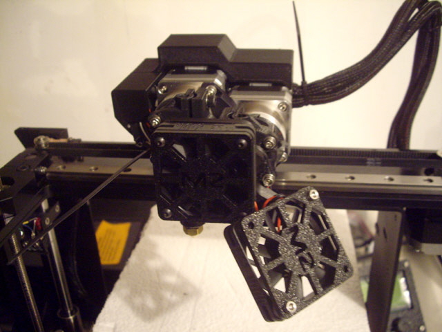
Figure 1. Dual Extruder Almost Completed
(Still to attach loom case and trim cable ties.)
The new parts have arrive and been fitted completing my Z stage upgrade
Trimming the cable ties on the dual extruder was easy, but fitting the cable shroud acceptably took some effort. Note that the shroud mounting bolts are necessarily longer than the originals. The new stainless steel bolts have hex heads which are infinitely preferable to the original black Philips head motor bolts.
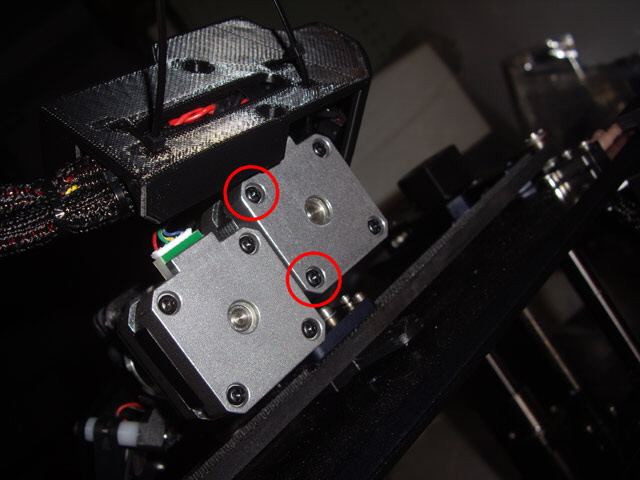
Figure 2. Shroud Mounting Bolt Locations.
Remove These Two Bolts from the Primary (Left Hand) Extruder
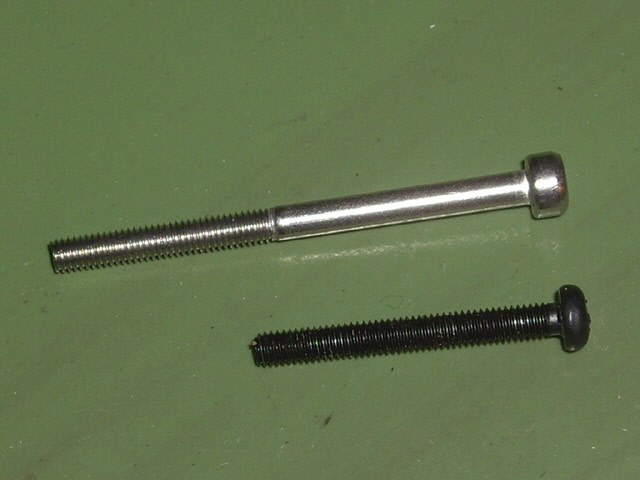
Figure 3. Shroud Mounting Bolt (above) and Original Extruder Motor Bolt
After fitting the shroud I found that there was inadequate clearance between the cable routing at he left hand side of the primary (left) extruder motor and the new low profile Z knob. I cut the ties and re-adjusted the location of the wiring flat to the side primary extruder motor housing.
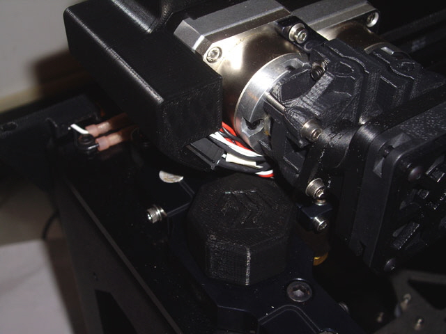
Figure 4. Insufficient Clearance between Dual Extruder Wiring and Z Knob
(The cable routing was reworked flat to the extruder case.)
When mounting the shroud take care to make sure that the wiring loom is clear of the mounting bolt lugs. First I loosely fitted the new cable ties and inserted the mounting bolts in the shroud.. Then I adjusted the loom for a clean, no-force fit with no exposed wires, no cable pinching under the shroud, no cable stress, and as much clearance as I could get between the wires and the Z knob. Then I engaged and seated the shroud mounting bolts and finally tightened the cable ties.
Note. There you may be confused by the extruder motor wiring described in the MakerGear dual extruder guidance, the original M2 wiring instructions, and the RAMBo manual. The guidance advises that the red wire on the the new extruder motor (E1) plug should be towards the front of the RAMBo in accordance with the RAMBo manual (image below). This is correct. If you get this wrong then the secondary extruder motors will still work, but in the wrong direction (retracting instead of extruding) and it will be impossible to load filament. The primary extruder motor (E0) has the red wire to the back in accordance with the original wiring instructions.
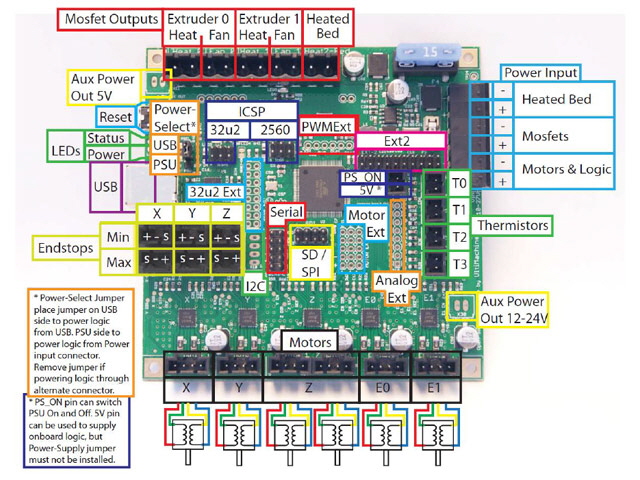
Figure 5. RAMBo Manual Wiring
(Motor Plugs with Red Wire to Front)
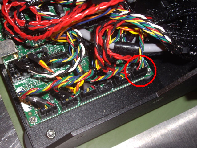
Figure 6. New E1 Extruder Connection (Polarity Red Wire to Front)
Note: E0 remains red wire to back.
The next steps are to level the bed and the extruder nozzles. With the bed level and within about 1 mm of the primary (left) extruder undo the secondary (left hand) extruder barrel clamp bolt located behind and under the filament fan (image below). The secondary extruder barrel should drop to the bed. Now manually raise the bed until it just touches the tip of the primary extruder and tighten the secondary (right hand) extruder barrel clamp bolt. The two extruder nozzle tips are now aligned in the Z axis.
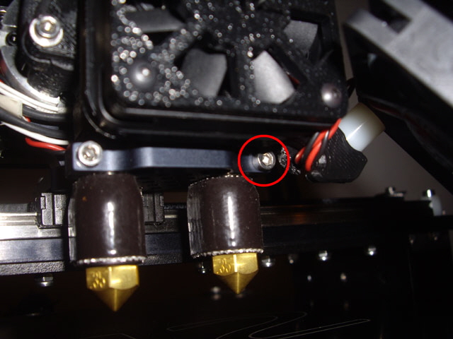
Figure 7. Levelling the Extruder Nozzles
I have some adjustments to make to the filament drives (see MakerGear guidance) and a RAMBo firmware upgrade to complete before I can be getting on and test the dual extruder. However the dual extruder hardware is now assembled.
With the firmware upgraded to the dual extruder Revision E version when the M2 is turned on the fans run only briefly until an extruder temperature reaches 50°C. You should see the temperatures for both extruders in Pronterface. Note that the electronics case fan must be connected otherwise the extruder fan will not run.
Slacken off the extruder drive tension bolts to both extruders.
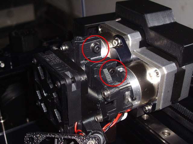
Figure 8. Extruder Tension Bolts
Now heat up the primary extruder (E0) to the recommended temperature for the filament. Then feed about 30 mm of filament into the extruder and then retract it fully. Examine the drive indentations on the filament and iteratively tighten the drive until the filament has between 10 to 15% indent compression while maintaining a circular cross section. One and a quarter turns of the tension adjustment from initial seating were required.
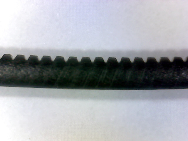
Figure 9. Correct 10 to 15% Filament Indent
(1.75 mm PLA on Extruder 0)
To repeat this on the second extruder issue the command T1 in Protoface in the command prompt at the bottom right of the Protoface Window. The Pronterface extruder widget will will now control the secondary extruder (E1). Follow the same tensioning procedure used for the primary extruder. A single turn of the tension adjustment from initial seating was required.
Before starting with a dual extruder print I decided to calibrate each extruder for layer height and width. A good model for this is a 20 mm x 20 mm x 5 mm high cube with a 2 mm chamfer on the vertical corners. The model is sliced with with single layer walls, zero infill and no top and bottom layers to produce a single filament thickness outer wall. Print with a first layer thickness of 100% (no compression).
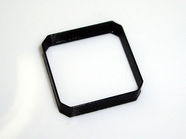
Figure 10. Calibration Shell using Primary Extruder (T0)
Measure the height and the wall width and adjust each extruder’s parameters appropriately. Then print the entire cube with 20% infill, two top layers. This tests that the infill does not cause distortion and also gives a better indication of bed adhesion than the wall.
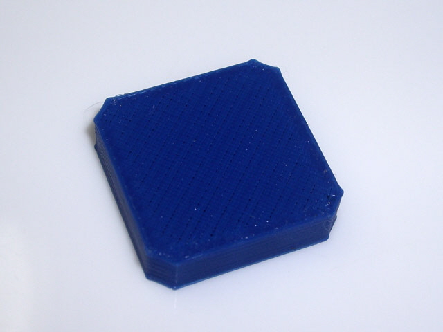
Figure 11. Calibration Solid using Extruder 1 (T1)
The calibration was pretty much spot on the default Simplify 3D parameters (within 0.05 mm). The only adjustment that I made was to the extrusion width which was 0.42 mm as opposed to 0.40 mm. Note that this parameter is primarily determined by extruder nozzle dimensions (and in particular orifice and tip diameter), and extrusion speed. Note also that the extrusion speed for this relatively small model will throttle back by 50% for infill layers if Simpify 3D calculates that a layer will take less than 15 seconds.
While completing the calibration I messed about with the Simplify 3D FFF files (Fused Filament Fabrication - in essence print profiles) to set up for printing from each individual extruder with an effective pre-print wipe and the model printing near the centre of the HBP. At the end of this process I have two good profiles for printing from either the left (T0) or right (T1) extruder.
With the individual extruders calibrated and it was time to try my first dual print. The first challenge was making a simple model for each extruded colour, and learning how to combine the models to coherent G code in Simpify 3D. The first print attempt failed due to Norton Antivirus starting background tasks during the last print layer and crashing the M2 USB communications. The following three attempts also failed due to issues with ooze shield bed adhesion. After slowing down the first print layer, adding a layer to the ooze shield width, adding a skirt, and slowing down the ooze shield print I managed to get my first acceptable dual extruder print.
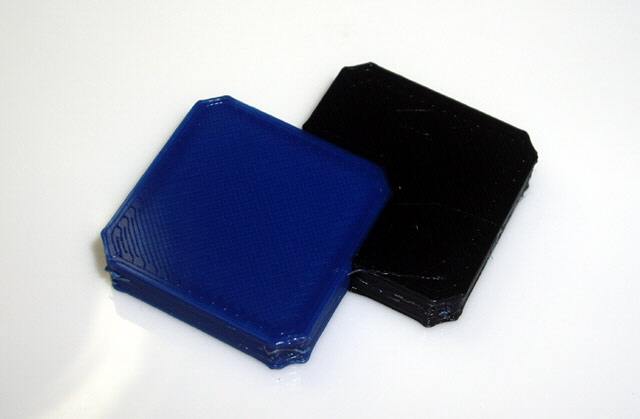
Figure 12. First Dual Extruder Print
The print is not perfect. The print speed for most layers was too slow (50% speed reduction for a later print time of less than 15 seconds) resulting in edge distortion. Some ooze also managed to get dragged through the shield (mainly because the print is so small that the idle extruder is not dragged over the ooze shield very often). And the X axis extruder offset is out by 0.1 mm. The print initialization also needs work to make for a more effective wipe on both extruders.
Note that inspection of the ooze shield is worth while. With this model the ooze shield actually gives a better understanding of layer alignment than the print object.
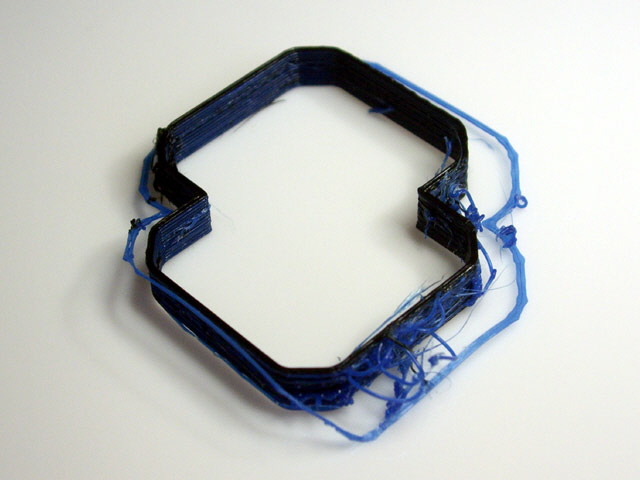
Figure 13. Ooze Shield
By noting the print orientation and measuring the wall thickness we can readily determine the required offsets. My filament extrusion width is 0.42 mm for each extruder so the total wall thickness of the ooze shield should be 0.84 mm (two layers). With the ooze removed the shield walls aligned with the X axis were almost exactly 0.84 mm. However in the Y direction the ooze shield width was 0.94 mm (with the blue filament from Extruder 1 to the right). So the Extruder 1 X axis offset needs to be increased by 0.10 mm to the left.
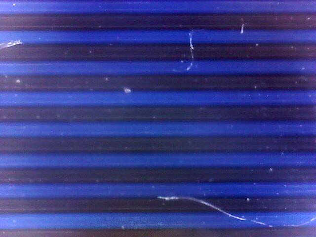
Figure 14. Ooze Shield Parallel to Y Axis with Good Alignment
(Note even blue and black filament width.)
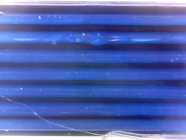
Figure 15. Ooze Shield Parallel to X Axis with Extruder 1 out by 0.10 mm
The alignment, bed adhesion and dimensions of the part are pretty good for a first effort. With a bit of print parameter tweaking I expect that I can get closer to excellent.
Notes on adjusting the second extruder (T1) X axis offset.
The M2 offsets for both extruders are set to firmware defaults on power on. The firmware defaults are X 0.00 Y 0.00 for Extruder 0 (T0) and X 31.10 Y 0.00 for Extruder 1 (T1). These values are not set in EEPROM and cannot be permanently changed without altering the source code. They can be read with the M code command M218 with no parameters, and adjusted with the same command followed by the tool number and the new values. For example M218 T1 Y31.20.changes the Y offset for Extruder 1 to 31.20 mm. This command should be placed at the beginning of the start-up G code script in Simplify 3D and saved as a new fff profile.
While it is also possible to change the tool offsets in the Simplify 3D GUI under G Code settings this will offset the graphical image of the model assigned to the extruder which doesn’t look too flash. Note also that the default Tool 1 offset in Simpify 3D is 31.10 mm but that the default settings do not apply these to the model G code. Do not apply these in Simplify 3D as they they will add to the M2 firmware offset settings.
Also note that Simplify 3D does allow you to specify printing a skirt with both extruders. I use this feature as it also acts as to reduce initial ooze.
Centring the model of the M2 bed is best done with global offsets which are specified in the Simplify 3D G Code tab. Print a centred object, measure the offset form the centre of the bed and simply enter the appropriate adjustments in the global offsets.
My test print is now at the centre of the bed, has correct extruder registration, and prints reliably without ooze issues. I’ve yet to try reducing the layer thickness to 0.1 mm and slowing down the outer layer to reduce echoes but no problems are anticipated here.
If you have any questions, comments or suggestions please email me. I will respond. Otherwise click here to navigate to upgrading the RAMBo firmware...
|