|
Okay, the cross slide nut on my lathe has been worn through use and abuse and is now excessively sloppy. I need to make a replacement.
I disassembled the cross slide and examined the state of the lead screw and the associated nut, measured the thread, and considered my options.
The cross slide lead nut is just a simple cylindrical brass boss with an internal thread but it has tight mounting limitations in the carriage casting. Any attempt to change the nut’s external dimensions will require some major surgery extending to grinding out the cast iron carriage.
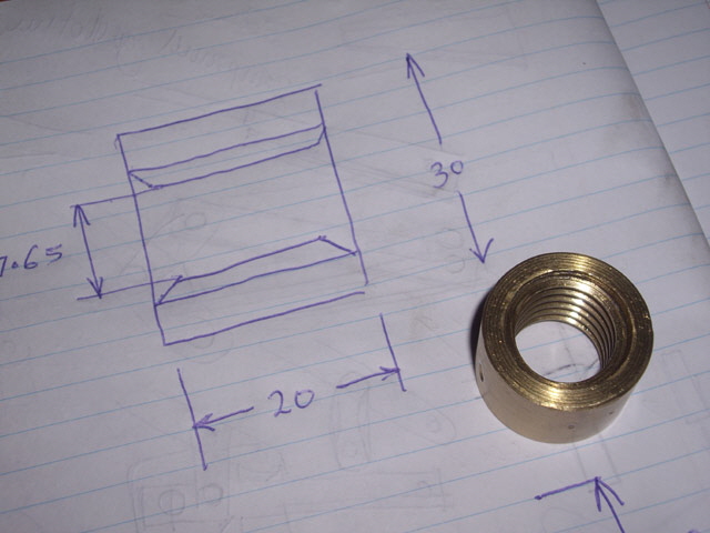
Figure 1. Worn Cross Slide Lead Nut
The cross slide lead screw is made of steel with what looks like a trapezoidal thread and a key-way. On examination the male lead-screw thread was pretty rough. Given that the nut is made of brass (and wears much faster than the steel lead screw) the lead-screw finish is probably due to poor original manufacturing.
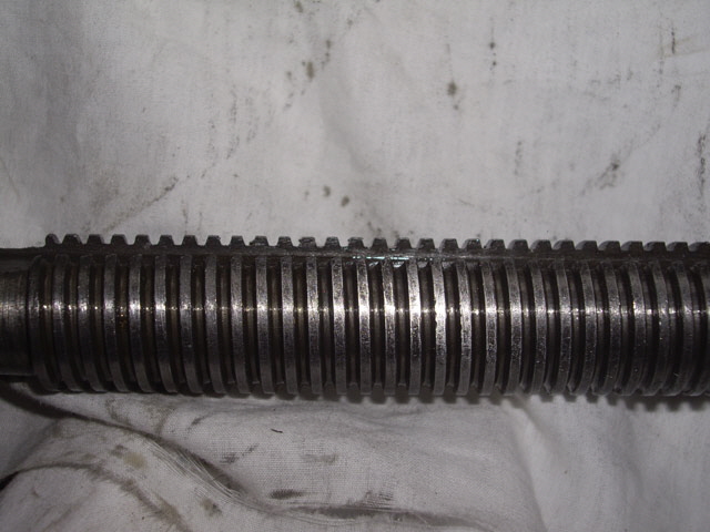
Figure 2. Cross Slide Lead Screw
The nut dimensions and mounting give me no scope for making a split nut or an adjustable locking nut so I guess I’ll be making a one-for-one replacement. I’ll be sticking with brass as this ensures that the nut will wear in preference to the lead screw which will be difficult to replace. In any case I’d like to have a spare nut because this single part is the weak link in the cross-slide drive and I dread actually breaking it because then I won’t be able to make a replacement.
The thread pitch is 3 mm. After a few macro photographs it is clear that the lead screw included angle is about 35 degrees (certainly not 30 degrees for a typical metric trapezoidal thread). The slop is clearly evident with the nut fed onto the lead screw and the nut thread is way too deep allowing a significant amount of play.
The next step is to design the nut thread based on the lead screw. The macro photos and the lead screw key way allowed me to get a reasonable thread profile which was easily scaled from the pitch. I want to make the thread tight. The sharp edges on the lead-screw key way will soon wear the nut to the exact profile. We are primarily concerned about axial slop as the lateral play is readily adjusted by the cross slide jibs.
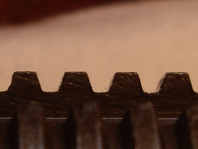
Figure 3. Cross Slide Lead Screw Profile
(3 mm pitch, with measured 35 degree included angle)
With the cross slide still disassembled it was time to make a thread cutting tool so I could match the profile against the lead screw. I have a collection of 3.2 mm diameter tungsten steel PCB drill shanks from broken drills that I have saved for this very purpose. These are extremely hard and will make excellent thread cutting tools when brazed to a robust steel tool shank.
I brazed the drill to a hand ground piece of square section mild steel. The brazing and grinding weren’t particularly tidy but they were effective.

Figure 4. Carbide Drill Shank Brazed to Steel Tool Shank
(see Figure 9 for ground profile)
Then I ground the thread profile on the tool using a bench grinder and a cardboard template to get the angles about right. The finished tool has a few degrees of side and front clearance and no top rake. A few checks against the lead screw and I was happy that the tool profile was about right.
With the tool made it was time to reassemble the cross slide with the old nut, re-adjust all of the jibs and lubricate everything. Many years back a colleague suggested that my lathe would probably die from rust before over-use. I clean it and wipe down the surfaces before starting any job and I clean and re-lubricate after every job. I lubricate all oil points at least every 12 operating hours. I check the gear box oil level, belts and jibs and give the machine a good shake-down (literally, to feel for slop, play, vibration or slip) from time to time. And I change out the gear box oil and inspect the gears every few years. If I detect an problem then I like to attend to it early.
The machine has a few dents and scratches and a minor machine mark on the compound slide (caused by an inadvertent lack of chuck clearance) but otherwise it is good order. While it may not be in constant use it will die from drowning in oil before rust.
Time to make the new cross slide nut. I have already cast some more brass stock. The machining should have been straight forward. Mount the brass stock, face it, turn it down to 30 mm diameter, centre drill, drill and bore out to 17.60 mm internal diameter. Part, reverse and face to 20 mm length. Mount the thread cutting tool, adjust the gearing, and cut the thread.
Of course nothing went quite to plan. Rather than turn one of my nice lumps of solid brass into swarf I figured there was enough clean material in the casting shrink off-cuts. I faced the off-cut, drilled it out to 13 mm, and turned about half of the exterior down to 30 mm diameter. Then I reversed the brass, centring it on the 13 mm drill, faced to length and turned down the remaining half to 30 mm OD. There was a very slight eccentricity with the OD as it had been machined from each end from a 3 jaw chuck, but this should be acceptable for this application.
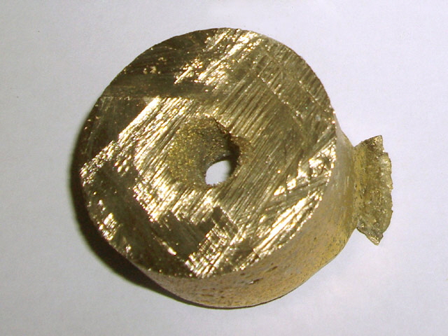
Figure 5. Brass Shrinkage Off-Cut
Then I set about making the thread. While I could do this under power feed the thread is quite short and I don’t want to risk an over-run of the tool holder into the chuck. My lathe does not have automatic stops or a brake. By taking small 0.10 mm feeds I set out to cut the thread by hand-turning the chuck.
After a total feed of 0.6 mm (well short of the required 1.45 mm) the tool fractured. I figure there are several reasons for this. With a perpendicular feed the amount of cut metal increases with increasing thread depth and hand turning the chuck makes for varying cutting loads. The actual tool was also quite long with zero top rake (as opposed to negative top rake for brass). I had not machined any run-in so the initial cut after a feed was probably quite harsh resulting in a sudden load. I may also have over-heated the carbide while brazing it to the tool holder.
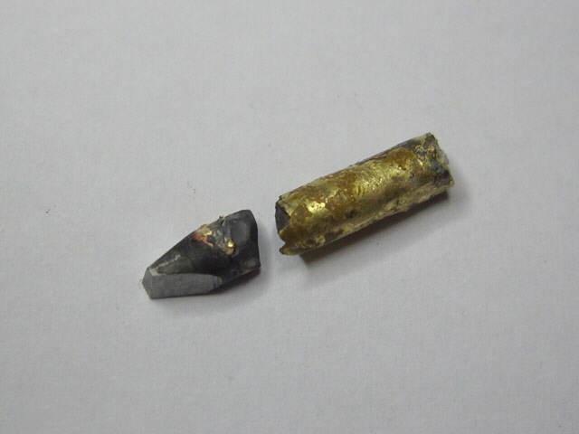
Figure 6. Broken Tool
The good news is that the partially threaded lead nut wasn’t buggered and the tool braze had not failed. I just needed to make a new tool with negative top rake, change the feed angle from perpendicular by just under 17.5 degrees and remount everything.
I heated up the steel tool shank and removed the remnants of the old tool bit, cleaned everything up with a file and a wire bush, washed the holder and the new drill bit stub in hot 20% sodium hydroxide for about 10 minutes, applied some home made white flux (2 parts by volume tri-sodium phosphate, 2 parts borax and 3 parts boric acid made to a thick paste) and re-brazed the tool, taking care not to apply any direct heat to the drill bit or the brazing filler.
While I was about it I also brazed an old saw tooth carbide bit into a previously damaged boring bar. The braze looks good. It will be interesting to see how this tool stands up.

Figure 7. Boring Bar Repair
(Carbide from old saw tooth)
Note: I have tried to use Silphos several times with and without flux on steel and carbide. Even with scrupulous cleaning and pickling Silphos just doesn’t wet these materials well and any resulting braze seems to be brittle. However regular brazing works well with white flux which I guess is why my cheap collection of fixed carbide insert tools are all brazed.
I machined a 17.5 degree lead-in on the nut body to reduce the shock load when initiating a thread cut.
Back to the grinding wheel. I have my original cardboard template as a guide but the wheel face isn’t looking too flash. I’ll attempt to dress it up using the end of an old file. I put about 10 degrees of negative top rake on the tool.
I re-setup the job in the lathe and completed the thread. When re-setting up a partially cut thread it is important to ensure that all drives are positively engaged (particularly the carriage lead screw) and the compound slide with the tool in about the correct position. I then use the tool post to ensure that the tool is appropriately aligned with the partially cut thread. The first cut is carried out with no compound slide feed to ensure that everything is where it should be. Any minor differences in the tool profile will disappear on the second cut.
With the new nut made I needed to disassemble the cross slide (again) and test the nut for fit. There were two problems. The nut external diameter is fractionally large and needs to come down from 30.05 mm to 29.95 mm. While I can force the fit I don’t want to risk damaging the cast iron carriage. And the nut thread is too tight. I figure it needs to be about 0.25 mm deeper. By making successive relatively light thread cuts and testing, I’ll end up with the desired tight fit even though I don’t actually know the required thread depth. I reassembled the cross slide, set everything up again, cut the thread depth an additional 0.25 mm and took 0.10 mm off the outside diameter.

Figure 8. New Cross Slide Lead Nut (left) and Original (right)
The carriage was disassembled for the third time but now the nut fits into the carriage and the lead screw engages tightly with the nut down its full length.
Once reassembled, and after a dozen bedding in traverses, the cross slide action is smooth and positive. There is no perceivable cross slide slop or play. However there is about 0.15 mm slop associated with the hand-wheel to lead screw drive. I might look at this later.
While nothing else needs fixing just now there is also some minor slop in the carriage feed and the compound slide. I can’t do much with the carriage because the slop is primarily in the drive gear train and would require new gears which I’m not really set up to cut. While I can make a new compound slide nut this will be a future project as it is not pressing just now.
Job done.
|