|
Perspex Construction
Refer to the drawings posted on this site for dimensions for the Pentax 750Z housing. All of the cases that I have made took a weekend of concerted effort and a few week nights to finish things off. This description is of my Pentax 750 camera underwater housing but the process is pretty much the same for all of my Perspex construction.
Make the sides of the housing body in pairs from 10 mm thick Perspex. Sand the edges to be glued flat, but do not polish them. Don’t get too hung up on tolerances. Remember that the adhesive will make everything slightly bigger. Work on getting opposite housing sides the same size.
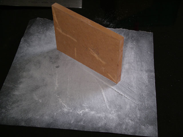
Figure 1. Sanding the Edges of the Back Straight and Square
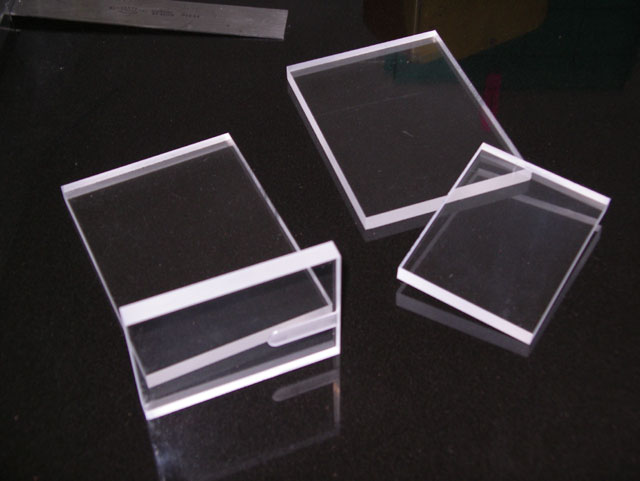
Figure 2. A Set of Sides
Keep as much of the Perspex’s protective paper in place for as long as you can. Mask the Perspex with tape to stop excess glue getting to where you don’t want it. Run a bead of glue along the edge of the sheet being joined and press the sheets gently together. Don’t apply too much pressure because it forces the glue out of the joint and leaves voids. Align the pieces of Perspex using an engineer’s square. Leave the joint under its own weight for an hour in sunlight to set. Acrifix 192 hardens quicker when exposed to UV light. I put the case in a light box (used for exposing printed circuit boards) for 30 minutes to complete the hardening of the adhesive. Remove the masking tape.
A Supplement for Really tidy Edges
If you use the above technique for joining edges you are likely to end up with excess adhesive beads on the inside corner of the seam. While this won’t affect the seal or strength it is unsightly, and being on the inside of the case these are difficult to sand off and polish flat. A better technique is to cut the mating edge at about 5 degrees and apply the adhesive directly from the tube from the outside of the clamped seam. Make sure to leave a bead of excess adhesive on the exterior as it shrinks as it sets and you want the hardened adhesive to be slightly pound of the surface where it can be readily sanded and polished flat. The following images show the process on a couple of small pieces of scrap.

Figure 2a. Unsightly Excess Seam Adhesive

Figure 2b. 5 Degree Angle Clamped for Adhesive Application

Figure 2c. Perfectly Clean Joint without Bubbles or Excess Adhesive
Now back to the assembly of my first Perspex camera case.
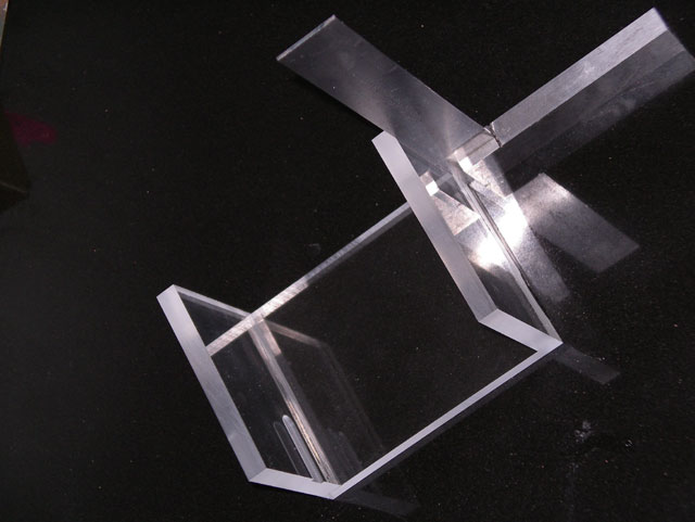
Figure 3. Aligning the Glued Sides
Assemble the sides of the camera body and sand and polish the joints flat with the faces. I used fine grade wet and dry abrasive paper on a granite flat plate. A sheet of plate glass would do just as nicely as a flat surface. Leave any excess glue at the joints on the inside of the case because it is tricky to remove it without scratching the inside of the case. Now sand the front and back faces of the case flat. When sanding and polishing take care to avoid over-cutting at the corners, particularly on the back of the housing. This needs to be dead flat for the gasket seal.
Cut two pieces of 10 mm thick Perspex about 10 mm oversize for the front and the back of the housing body. Machine the lens housing mounting recess in the front face taking care to locate it to align with the camera lens. Now align the sides of the housing body with the front of the case, again taking care to ensure that the camera lens aligns with the lens recess, and scribe the position of the sides onto the housing face. Trim the housing face to size and sand the edges flat. Check the alignment of the camera and lens again. Now glue the face to the sides as follows. Mask the edges of the joint. Run a continuous bead of adhesive around the facing edge of the sides, put the face in position and align it with the sides. Again don’t apply too much pressure, and carefully work any air bubbles out of the joint. Use the same drying procedure that you used for the sides. Remove the masking tape and sand and polish the edges of the case flat.
For the back of the camera housing I laminated a 3 mm thick piece of Perspex to the 10 mm thick back plate to hold the gasket in place. Cut the 3 mm sheet to size and check the fit with the front of the housing body. It should fit freely. Round the corners to a 5 mm radius with a file (because square internal corners don’t work well with gaskets). Sand the edges flat and smooth. Now mask the back plate to fit the 3 mm sheet central. Put some adhesive on the back plate taking care to exclude air bubbles. Put the 3 mm sheet in place leading with one edge to exclude air bubbles, and position to align with the masking tape. Apply moderate even pressure to the laminated sheets and dry as above. Remove the masking tape and carefully clean up the edges of the laminated sheet, avoiding scratching the Perspex as this will be a sealing surface for the gasket.
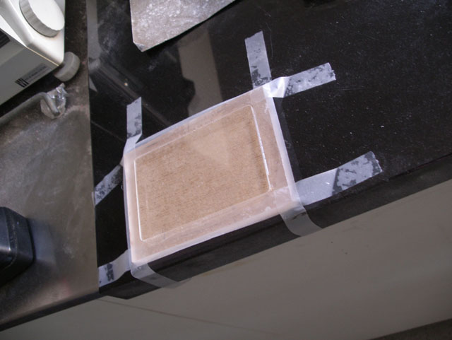
Figure 4. Masked and Laminated Back Plate
Place the back plate on the housing body and scribe the size. Cut the back plate to size and sand and polish the edges flat. To prevent stress cracking of the laminate adhesive provide lots of support by clamping the backing plate between pieces of MDF while cutting.
Mark out and drill the 2.5 mm diameter holes for the back plate mounting studs with the back in place on the housing body. Tap with a 3 mm bottoming tap. Then over-drill the holes in the back plate out to 3.5 mm diameter to ease getting the back plate on and off .
Cut the gasket to size from 1 mm thick EDM rubber sheet using the back plate of the housing as a template. Use a cork borer for the internal corners and stud holes. Cut the sheet using a sharp scalpel blade against a steel rule.
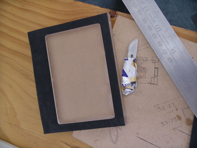
Figure 5. Making the Gasket Using the Back Plate as a Template
The housing body is now largely complete. Clean and polish it, removing any unsightly scratches and excess adhesive. Use self-adhesive rubber feet, double-sided adhesive foam tape, and rubber strips to make the camera fit securely in the housing.
I machined the lens housing from a 60 mm diameter 50 mm long piece of grey PVC rod. Turn the outside profile and check the fit with the housing body recess. It wants to be a free fit to ensure that there is some space for the adhesive. Bore the housing and machine the lens seat taking care to get a good surface finish. Face the lens housing to length.
Cut the lens from 6 mm Perspex sheet. I roughed out an oversized hexagon, mounted this on cardboard in a three jaw chuck, and carefully cut the lens blank using a facing tool. The lens was parted from the sheet with just 0.1 mm of cut left to make by turning the chuck by hand and slowly feeding a sharp pointed facing tool into the work. Check the fit with the lens housing. If all is well, machine the O ring recess in the lens.
The 1.6 mm diameter holes for the 2 mm diameter lens retaining screws were drilled through the lens and the housing using a dividing head to get them spaced evenly and on centre. Remove the lens and over-drill the holes through it to 2 mm diameter. Tap a 2 mm thread in the holes in the lens housing and deburr. Clean and polish the lens.
Machine the control buttons from brass rod taking care to get the O ring groves in the right place and of the right dimensions. The control seals depend on these. Remove any burs on the recesses with a flat file. Make the controls about 3 mm longer than necessary and turn to length to leave about 1 mm between the end of the control rod and the camera button. For springs I used 0.25” OD 0.02” thick utility compression springs cut to 12.5 mm. The O rings were 5 mm OD, 1 mm thick.
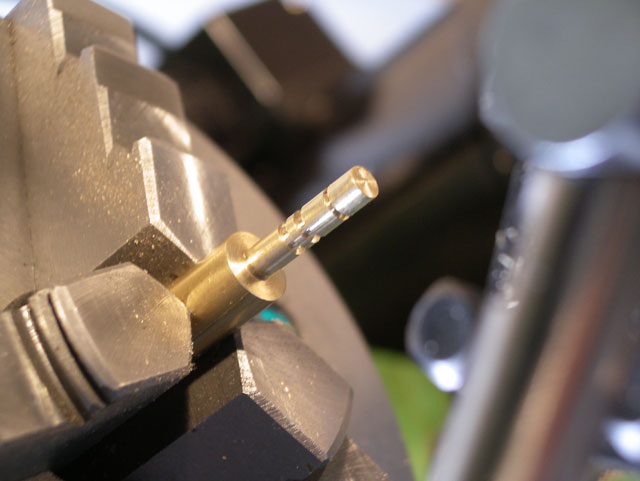
Figure 6. Machining the Controls
Machine the vent plug and strap mount from brass rod. I cut the threads using an M6 die.
Mark out and drill the 4.5 mm holes for the controls in the housing body. Don’t try and get the position by eye because refraction through the Perspex may result in the holes being off centre. Polish the holes with metal polish on the drill shank turning slowly in the drill. Cut a 45 degree chamfer on the outside edges of the hole to allow the O rings to be fitted without damage.
Mark out, drill and tap the holes for the vent plug and strap mount.
Fit and mount the studs to the back of the camera. I used 3 mm diameter stainless steel threaded rod cut to length, but 30 mm long machine screws will work just as well with the heads ground off. Don’t overrun the tap as Perspex is pretty unforgiving – you will strip the thread or crack the case. Use two locked 3 mm nuts to insert the studs into the back of the housing onto a drop of cyanoacrylate adhesive.
Now glue the lens housing into the recess on the front of the housing body. Mask everything and apply a bead of Acrifix 192 glue around the recess. Position the lens housing and apply a moderate weight (1 kg) until the adhesive has cured. Remove the masking and clean up any excess adhesive.
Fit the controls using a small smear of rubber grease.
Fit the vent plug and the strap mount. I put a drop of cyanoacrylate adhesive in the strap mount hole before screwing it into position.
Clean everything again. Now fit the lens using the lens O ring and screw into position with 2 mm stainless steel machine screws.
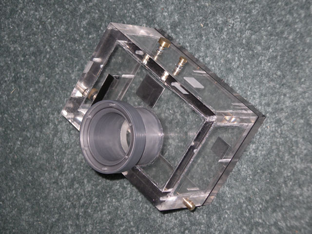
Figure 7. The Case All but Complete (Lens Screws and Back Plate Studs to be Fitted)
Now test the housing at the planned depth with plenty of control manipulation and without a camera (just in case).
|