|
I have a bunch of machining to do that will require extensive use of the compound slide so it’s time I set about replacing the compound slide nut to reduce the slop. The slop is currently a tad over 1 mm
This part is just a bit more complicated than the cross slide nut that I made earlier. Figure 1 shows the original. Note that the nut is brass and will wear preferentially over the steel compound slide feed screw.
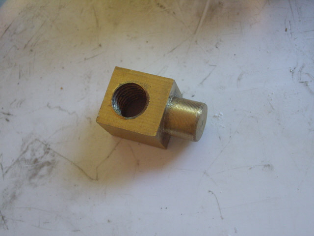
Figure 1. Original Compound Slide Nut
There is room to increase the threaded length of this part from 15.5 mm to about 25 mm which will reduce the wear rate. The compound slide feed is 2 mm per turn so this gives the thread pitch. I used a macro photograph to estimate the thread profile.
Figure 2. Co m[pound Slide Lead Screw Profile (2 mm Pitch)
The boring bar I made for the cross slide is too large for this job so I’m going to have to make a new one. Rather than braze the tool bit to the bar I’ve decided to make a grub-screw clamp for the tool bit in some 8 mm diameter steel rod, and mount this in the tool post using an IFanger micro-bit mount. This will be far more useful than a fixed brazed bit for small work, and longer and more stable than my IFanger boring and thread cutting tools.
Machining the boring bar was straight forward from an old laser printer cartridge roller. Cut to length. Square up the ends. Drill the tool bit hole for a push fit to the tool blank. Now drill and tap for the grub screw (I used a hex M5 steel screw).
Next I ground the tool (an old broken tungsten carbide PCB drill shank) to the thread profile using a bench grinder. Remember to duplicate the male thread profile (Figure 2) with a slight reduction in tip width. The new nut is brass so we want zero or slightly negative top rake, with about 5 degrees of end and side clearance.
With the tool ground the shank needed to be cut to the diameter of the tool holder. The best way to do this is with a diamond cut-off wheel on a Dremel. While you can score an break the carbide, it won’t always fracture cleanly and may ruin the tool bit.
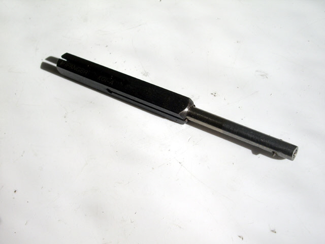
Figure 3. New Boring Bar
Time to measure up the old part. That’s weird, the pivot is not concentric with the thread? I figured that the nut pivot should be on centre line of the nut thread and set out to machine it accordingly.
Machining proceeded as follows. From round brass stock face and then turn the pivot in a three jaw chuck. Reverse the stock, part and turn to height. Mill the four flats off the sides of the pivot to ensure the pivot is on centre. Mark out the centre for the threaded hole. Using a four jaw chuck centre the part, counter drill, and progressively drill or bore to the 10 mm root thread diameter. Then cut the thread with a tool feed of slightly less than 17.5 degrees (15 degrees is good) to fit (a feed of just over 1.1 mm).
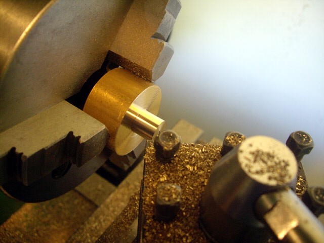
Figure 4. Turning the Pivot.
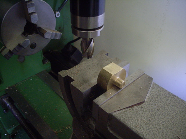
Figure 5. Milling the Flats.
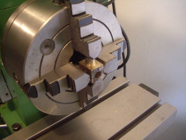
Figure 6. Drilled Root Diameter Hole for Thread
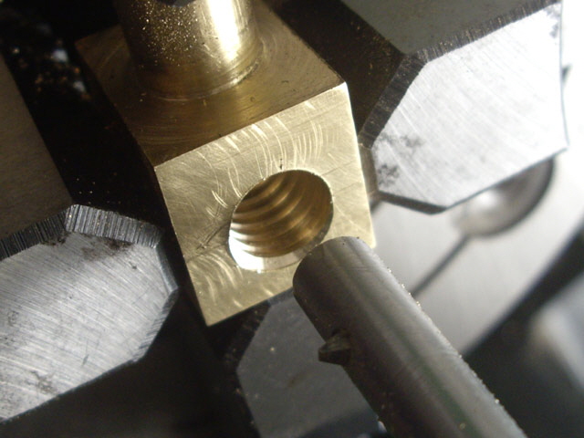
Figure 7. Boring the Thread
With the new part finished it was fitted and tested. The thread was a little tight (fine- it will bed in), but a major issue was that the cross slide was about 0.2 mm horizontally off the seating vee bed and the compound slide action was far too tight. Bugger! The new thread is exactly on centre (within 0.05 mm) and was forcing the compound slide carriage to crab on the vee bed.
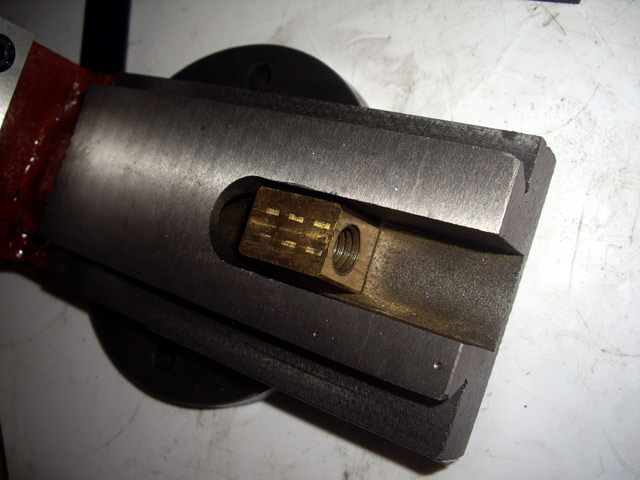
Figure 8. New Compound Slide Nut Fitted
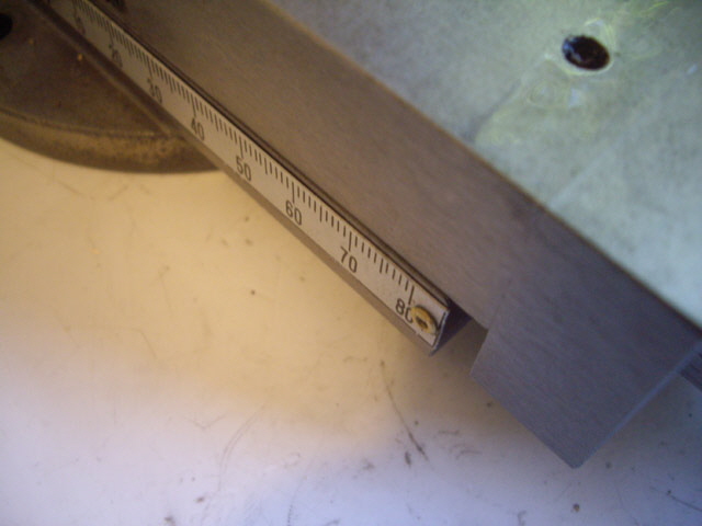
Figure 9. 0.3 mm Crabbing on the Vee Bed
Time for some more measurements. The cross slide feed screw is 0.3 mm off centre from the cross slide nut pivot! From time to time you’ll find jobs where stuff doesn’t align as you intuitively expect (in this case the threaded hole off centre). Rather than try and fix the original problem you are better off to make the part to fit.
The old nut had at least 0.2 mm clearance in the thread and the thread was offset 0.13 mm from the pivot. These clearances combined with the shorter engaged thread length allowed the compound slide to sit true with the bed. This might also explain why the part has worn out relatively quickly. The lead screw was probably only in contact with the outer threads of the nut.
Perhaps I can fix my new part by brazing the pivot and re-turning it off centre? I tried and failed – getting the part too hot and partially melting the pivot.
So I need to make a new compound slide nut with the centrelines of the thread and the pivot offset by 0.3 mm. My second attempt failed on two counts. First I got the pivot diameter slightly under size due to too much play in the compound slide gib (caused by inadequate re-assembly after testing the previous thread fit). I managed to repair this with the brazing technique that had failed previously so I progressed on to cutting the thread.
While I have a drawing and minimum dimensions I am making the thread to fit which requires pulling the cross slide apart to test the new nut, and removing the nut from the four jaw chuck. Everything needs to be reset before another cut. During the second reset I managed to get the tool alignment wrong and my thread disappeared in a single cut!
Okay, I’m back at square one and now I’m out of suitable brass stock. I have some on order and hopefully this arrive in a few days. The stock has arrived and I’m ready to turn some more useful brass into swarf.
The third attempt and another failure. The pivot diameter was fractionally too small – a basic machining error on my part.
The forth attempt was excellent until I buggered the thread again! After thinking about what I’m doing so wrong I suspect that the problem is with reverse power feed of the boring bar. The back-lash in the gears to the lead screw is a full quarter turn of the head stock. So on each reverse power feed I’m chewing up almost a quarter of the thread pitch if the tool isn’t fully withdrawn from the thread. I need to back the tool off the full feed depth to prevent this in future.
My usual internal thread machining technique is to lock off the cross slide and do all feeding and backing off with the compound slide. Some folk use the cross slide for backing off with a set datum (say zero) and use the compound slide for the thread cutting feed. While this works, the fewer moving parts involved the process the less likelihood there is of making an error or additive tolerance.
The other hassle is having to disassemble the compound slide to check the thread fit. So I made a male thread to match the lead screw from a piece of scrap 14 mm round stainless steel bar. Aside from grinding the tool this was remarkably straight forward. If I really get stuck making the thread I’ll grind some slots in this piece and use it as a tap!
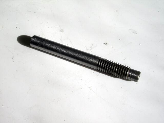
Figure 10. Dummy Lead Screw Thread for Testing the Nut Thread
I’m going to persist with making this part, if for no other reason than to improve my machining technique.
While my current machining operation is relatively straight forward it turns a lot of brass into scrap. While I could modify the machining process to use about 50% less stock the increase in machining difficultly (and in particular the need to turn a rectangular section circular with shock loading of the tool) doesn’t warrant a change.
The new part has been made at last. The dummy threaded rod was really useful in getting a good thread fit with without the hassle of disassembling the compound slide for testing and then trying to re-align everything.
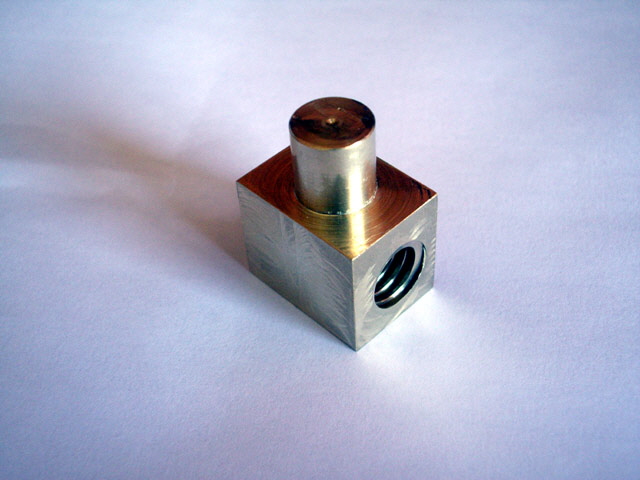
Figure 11. The Finished Replacement Compound Slide Nut
With the new compound slide nut fitted the slop has been reduced to less than 0.1 mm (and most of this is associated with the collar bearing). The compound slide action is dead smooth. And as a bonus I now have a new boring bar and a spare (if somewhat worn) compound slide nut.
Job done.
|