|
The entire purpose of having a CNC mill is to actually make stuff, so best I get on and actually try turning perfectly good stock into swarf!
Before I can get on and mill something I need a flat spanner to undo the collet chuck. WMT didn’t provide a tool for this. Making a tool would be a great profile milling job, but you need the tool in order to use the CNC mill. I drew one up on 6 mm aluminium plate and cut the profile with a hack saw and a range of files. It isn’t perfect but it’s functional.
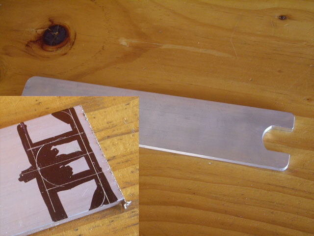
Figure 1. Flat Spindle Spanner
Real Milling
I have already run the tool path so I’m confident that the CNC mill will cycle through the tool path without doing anything untoward like plunging into the bed. Here is the procedure I used for setting up the job.
- First, rough the stock to size based on the model. Then mount the stock on a sacrificial bed (MDF) and bolt this to the bed near the centre (clear of any home or axial limits). I’ve used the glue and masking tape method to attach the stock to the sacrificial bed. It appears to be very secure but it is not mechanically positive (more on this shortly).
- Turn on the control computer (Mach3), reset, and load the numerical control file. Power up the XK7113D CNC mill.
- Home the axes under Mach3. This ensures that the machine will work within Mach3 soft limits (which should be turned on) and should not crash into anything.
- Using a centre in the collet chuck, use Mach3 jog commands align the stock edge parallel with the X axis. Then move to the model X,Y origin (0,0 which for this model is at the left hand front of the stock. Now zero the G58 X and Y coordinates at this point. Note that it is almost impossible to find centre with a cutting tool in the chuck. This particular model has 1 mm of stock around the parts so this is the tolerance for establishing parallelism and the origin.
- Secure the milling cutter in an appropriately sized collet in the chuck, and jog Z to the top of the stock. I use a piece of paper at 0.08 mm thick for this purpose. Jog down to sliding friction on the paper. Remove the paper, jog X or Y off the stock, and jog down 0.08 mm. Now zero the G58 Z axis followed by jogging up to a safe height above the stock (say 20 mm).
While this sounds complicated and time consuming the entire procedure takes just a few minutes.
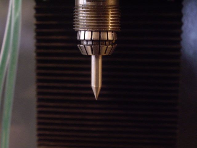
Figure 2. Needle Sharp Centre for Locating X/Y G58 Origin
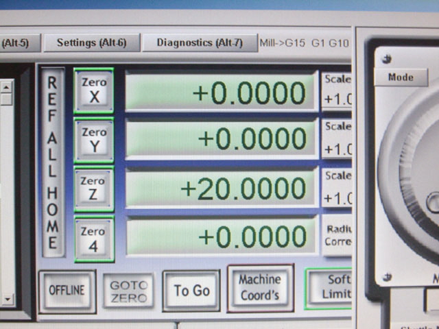
Figure 3. Homed and Zeroed Ready for Milling
Put on your safety gear and start the job machining using Cycle Start (Alt R) in Mach3.
On the first attempt the 3/16” four flue end mill was forced up into the collet chuck on the first plunge cut. So the Z axis was now not correct and all further milling was with the milling cutter bottomed out in the chuck. Swarf appeared to weld to the cutter resulting in rough cutting. The stock became very hot very quickly. I let the machine cycle through to the end of the GCode during which time the tool seemed to clear of cold welded swarf. The chips (no dust) appear to be well-formed and have thrown clear of the stock.
I hadn’t allowed enough time for the spindle motor to get up to speed before the first cut, and maybe I hadn’t adequately tightened the collet chuck. (There were other, more critical, failures that were’t apparent until after the failed second attempt and a review of the videos.)
I checked the tool and it looked to be okay. So I firmly reset it in the collet chuck, removed the burrs from the top of the stock with a file, re-zeroed the Z axis (without touching X or Y so I could over-cut the previous attempt), increased the spindle turn-on delay to 20 seconds through the Mach3 Config/Ports and Pins/Spindle screen, and reran the job.
Note: This turn-on delay is too long. Ten seconds is more than adequate to accelerate from 0 to
12,000 RPM.
The job started just fine but near the bottom of the first hole the stock came loose from the sacrificial bed, the tool broke, and the stock shot off the bed. A near miss?! – Nah! It hit me in the smack in the belly. Oops. The physical injury isn’t severe, but my pride has taken a big hit and I almost died of embarrassment.
Note: The disaster happened so quickly that I didn’t have time to react and hit one of the stop buttons on the keyboard or on the machine.
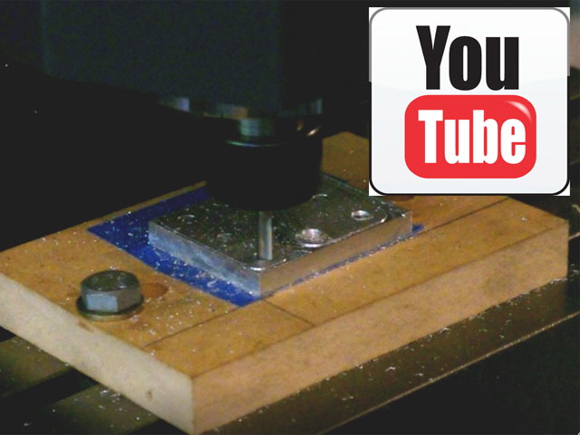
Figure 4. Second Attempt
Inspection of the damage confirms a broken tool stuck in the stock, a tear in through the outer layer of my jacket at the point of impact, and a graze on the left side of my stomach with a bruise rapidly forming.
Inspection of the stock shows that the surface profile cuts are beautiful (absolutely no catching with a finger nail test) and showing a slight refraction pattern, the profile and hole dimensions are pretty much exact (within 0.02 mm) less some slight roughness on the profiles. So the experiment crashed and burned but the machine is cutting metal very efficiently on lateral passes.
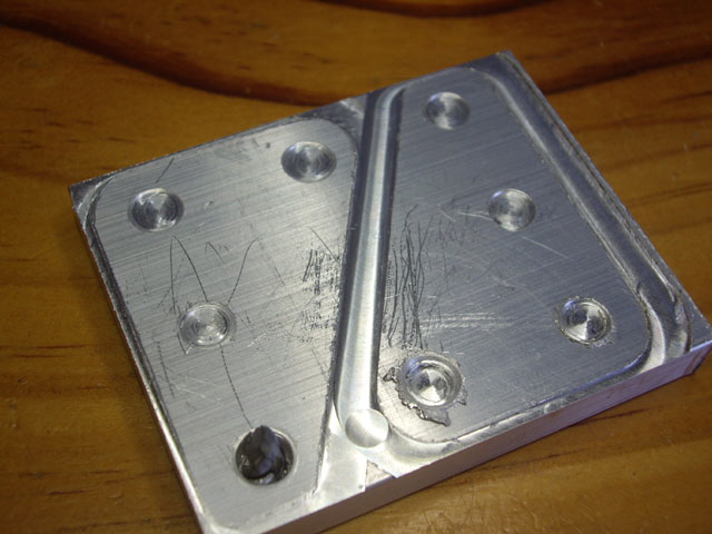
Figure 5. Tool Stuck in Stock and Beautiful Horizontal Surface Finish
(The scratches are from my crude deburr after the first failed attempt.)
Interestingly the masking tape and super glue remained intact on the sacrificial bed. The masking tape has actually been burnt at the point of failure which shows just how hot the stock was getting during the plunge cut.
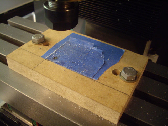
Figure 6. Masking Tape Intact and Burnt (Left Corner)
A review of the two videos shows that the stock begins to move on the sacrificial bed within four seconds of commencing the first plunge cut. This is in part down to the very rapid heating, and in part due to the aggressive helical plunge cut with a four flute end mill. With the stock moving about the machined profile finish was never going to be perfect.
The primary reason why the end mill was forced up into the chuck on the first attempt, and the stock detached in the second, is attributable to helical plunge cutting too aggressively with a four flue end mill. These tools are not capable of aggressive plunge cutting. This created a tremendous amount of heat very quickly, and at the bottom of the first hole on the second attempt the tool deformed the aluminium, lifting the stock up off the sacrificial bed. The stock then jammed on the end mill and stalled the spindle. As the tool retracted it took the stock up with it, tearing it loose from the tape (aided by the heat in the stock). The tool and stock then began to rotate about the tool axis which is well away from the centre of gravity. The tool probably broke due to eccentric loading, and without mechanically positive restraint it became airborne.
The mill is trying to force the centre of the of the 3/16” carbide tool through an aluminium plate with brute force and actually doing a remarkably good job of it. Hang on, haven’t I been here before (I had the very same issue with my toy hobby mill). Several quotes come to mind.
Anon: ‘A fool leans by his own mistakes. A wise man leans by a fool’s mistakes.’
Master Yoda (The Last Jedi): ‘Strength, mastering. Humm. But weakness, folly, failure also; yes, failure most of all. The greatest teacher, failure is.’
I guess I am a slow learner.
The adhesive and tape fixing actually performed remarkably well. Sure, it moved under lateral loads but only when the aluminium became really hot due to the plunge cut with a four flue end mill. Notably it did not detach until after the spindle stall, and then only when the spindle started to retract. This was probably aided by the significant stock deformation at the point of breakthrough.
So I need to use a two or three flute end mill for this job, perhaps with a reduction in the helical plunge rate. This should enable plunge cutting and keep the stock temperature sensible. The tool diameter also needs to be reduced slightly to between 60 and 80 percent of the hole diameters to ensure ready chip clearance.
Some form of flood or spray cooling would help keep the stock (and adhesive) from getting hot. It should also improve the surface finish and prolong the life of the tool.
As a priority (to avoid further embarrassment) I need to fit polycarbonate machine guards, particularly at the front and sides to protect the operator and the computer monitor from errant parts, swarf and eventually cutting fluid. No more milling trials until these are in place.
And I’m thinking about improvements to the stock mounting – probably end clamps combined with the tape and adhesive. The down side of this arrangement is that it will result in increased waste, but it should assist in keeping the stock secure to the bed.
The new machine guards have been fitted and the new three-flue end mills have arrived. I have also procured some new relays for reconfiguring the control cabinet for spray cooling. I’m just waiting on the cooling pump and nozzle before I’m back in action.
Click here to link to Machine Guards.
Click here to link to Spray Mist Cooling
I’ve sorted the machine guards and spray mist cooling, and completely rewired the control cabinet. I’ve also reworked the numerical control model for my current project, but I need a fixture for secure, accurate, rapid mounting of the stock. It took a day to design and fabricate.
I’ve used aluminium for the clamps just in case there is a disaster, but they deflect a tad under clamping load. I may need to remake these from thicker stock or steel.
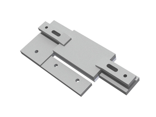
Figure 7. Fixture Design
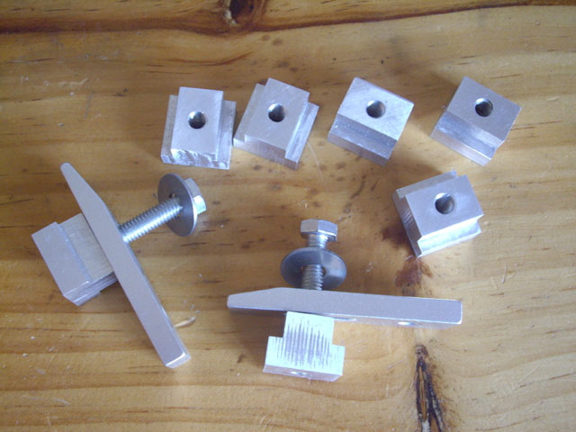
Figure 8. Seven Tee Nuts and Two Clamps Fabricated from Aluminium
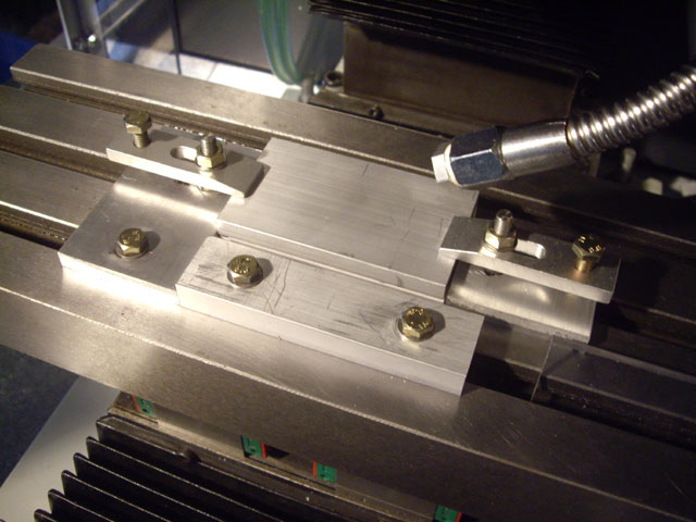
Figure 9. The Completed Fixture
The new fixture ensures fast, accurate and secure positioning of the stock. It takes less than a minute to demount the old stock and remount new. The fixture will also accommodate a longer stock length eventually allowing for six parts to be machined in a batch, reducing waste material. The front of the stock is spaced off the fixture using a slip-in 6 mm Perspex spacer because the tool path passes through the front and back of the stock and I don’t want to damage to the fixture.
Everything is clamped securely using M6 studs and bolts, and the stock is adhered to a reuseable Perspex sacrificial bed using masking tape and Super Glue (as before). This allows the final roughing and finishing passes of the part external profile without stuff becoming air borne. It takes just a few seconds to tape and adhere the stock to the Perspex. With the cutting fluid spray mist I can’t use MDF because it delaminates quite quickly. The stock and sacrificial bed are clamped vertically and positively located in the XY plane. It cannot rotate or lift.
I am going to XY zero the machine and run the tool path 20 mm above the stock to make sure nothing inadvertently crashes into the fixture, clamps or the bed before actually cutting metal, and that the CNC sequencing of spindle ramp up, spindle cooling and cutting fluid are right. While the Fusion 360 tool path simulation already demonstrates that crashes shouldn’t happen, I’ll sacrifice the time and add to the surety.
The first attempt managed to cut the holes really well but failed on the first profile cut with the tool shank breaking. This has to be due to the XY feed and depth of cut. A quick check with an on line calculator and
1,300 mm/min to way to high. Looks like I’ve made a mistake in my calculations. With the feed rate adjusted to a more modest 500 mm/min and some new stock mounted I have completed my first real machining job on the new mill.
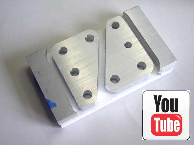
Figure 10. CNC Milling at Last!
(Click on the image to view the machining.)
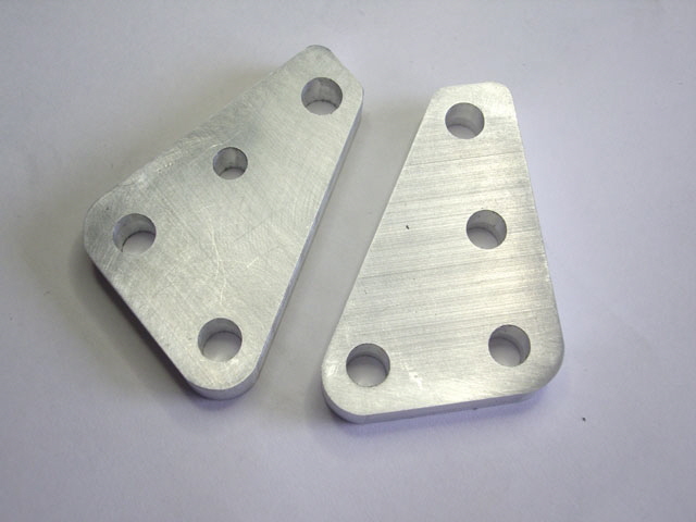
Figure 11. Useful Parts
The profile surface finish isn’t perfect due to chatter marks, but the hole diameters, centres and profile dimensions are within 0.05 mm (0.002”) of the model, and with a superficial clean-up the parts are fully functional. I’ve got some work to do on the numerical control to get the machining time down and improve the surface finish.
More to follow...
|