|
With the furnace refractory drying we can start on the burner. My initial concept was to use a commercial Primus LPG torch but there were two problems with this. The jet in the Primus jet is extremely small (about 0.2 mm in diameter) and will not supply enough LPG for the desired heat output, and the Primus nozzle is made of brass and this is likely to melt at the intended furnace temperatures.
There are some excellent references on burner design and a number of ‘instructables’ on the internet. I recommend ‘Gas Burners for Forges, Furnaces and Kilns’ by M. Porter, Skyjack Press, 2004. The book provides a number of burner designs as well as generic design advice.
Rather than use plumbing fittings I set about machining my own burner from stock steel, brass and aluminium. While I clearly want an efficient burner there are some over-riding considerations:
The burner must fit inside the 23 mm ID steel burner tube cast in the furnace refractory with clearance for thermal expansion.
The burner must connect to my existing LPG torch hand-piece. This means that I won’t need to purchase additional gas fittings such as a needle valve or regulator.
The burner length should be approximately 10 times the barrel ID (for gas/air mixing and turbulence control).
The burner should be fully adjustable.
The burner nozzle should be located about 25 mm clear of the furnace cavity.
With these requirements in mind I set about machining the burner parts. These presented a few challenges.

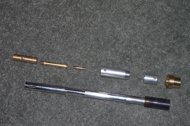
Figure 1. Burner Parts
Drilling the jet (two jets were made at 0.5 and 0.6 mm diameter) required the use of tungsten micro-drills that I use for printed circuit boards. Feed rates are necessarily slow at high RPM. I managed to break one drill on my first attempt, assigning that nozzle to the scrap bin (oops).
The Primus torch handle has an M8 x 0.75 external thread. I machined the matching internal thread on a lathe as I don’t have a suitable tap for this. All other combustion train component connections were made using metric taps and dies.
The combustion air slots were milled in the barrel body (as opposed to hand-drilled and filed). I couldn’t find an 8 mm milling cutter for this job so I machined eight 3 mm diameter slots, each 40 mm long, as opposed to four 8 mm slots. In retrospect the larger width slots would have performed better.
The steel tube that I used for the burner barrel and the furnace burner sleeve were taken from 16 mm and 25 mm OD chrome-plated shower rails. This tube is not ideal as it has welded seam construction, but it was cheap. The welded seam was cut back to the basic ID with a boring bar and filed concentric with the bore.
The flare proved to be the most critical part of the burner design. The burner performance was somewhat sensitive to the flare location and profile. I ended up making a number of flares with both steps and 5° tapered profiles and compared their performance. The final flare design permitted the burner to be adjusted from an oxidizing flame to a reducing flame with a stable jet flame from an almost fully closed needle valve to fully open. The flare is a tight press fit on the burner barrel. Provided they stay in good thermal contact the flare should not separate from the barrel due to thermal expansion.
Note that there is no gas regulator in my combustion chain. Gas flow is controlled entirely by the needle valve on the hand piece and the size of the jet orifice .
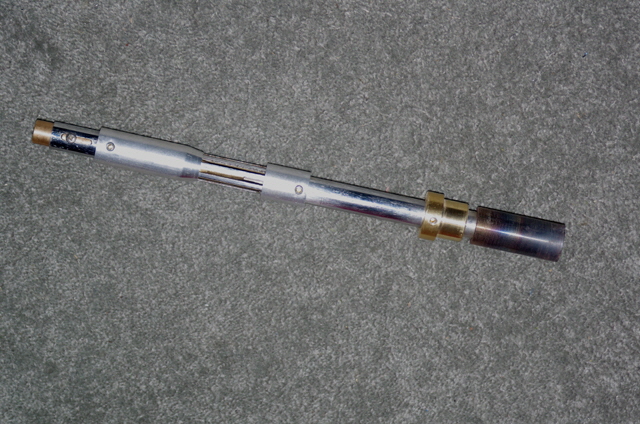
The design was completed with a spacer with end stop to ensure that the burner assembly could be securely and consistently located in the furnace about 25 mm back from the furnace cavity.

Figure 2. Burner Assembled
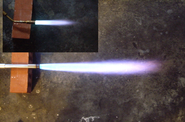
The burner was tested. It operates magnificently although it did set the smoke alarm off in the workshop after less than a minute at full gas flow. Having played with the adjustments the performance could be improved by increasing the air intake area and the flare diameter.

Figure 3. Burner Operating
(Insert is original Primus burner)
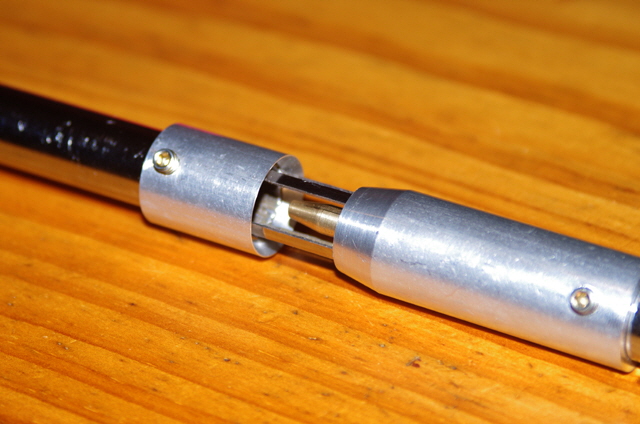
I can’t increase the flare diameter due to the mating furnace burner port, and providing more intake air will significantly weaken the strength of the burner barrel. After some deliberation I carefully hand-filed every second land off the air intake ports. This makes for four 8.2 mm wide vent slots as opposed to eight 3 mm wide ones with a 40% increase in actual vent area (the aerodynamic vent area is appreciably smaller than the actual vent area). I can’t get any more aspirated air flow without significantly reducing the burner barrel strength, incorporating a venturi, or entirely redesigning the venting port.

Figure 4. Improved Air Intake Ports
(Every second land removed)
The modified air intake is a significant improvement on the original and allows for a much wider range of combustion air control for a given needle valve and jet orifice.
If you want detailed drawings of my burner please email me.
Time to make a crucible. Please click here.
|