|
With my weld head built it’s time to get on and repair a bunch of battery packs. I have a heap of nickel strips and replacement sub C (and 3/4 sub C) NiCad batteries.
Note that I always weld with safety glasses on and (when I remember) take my wrist watch off. While good welds do not result is excessive sparking or splatter, poor weld contact and high discharge current can result in hot sparks going all over the place. I don’t want this in my eyes. And I have already destroyed my wrist watch once with this welder due to EMP!
I started with the simplest batter pack. A very old Black and Decker Drill that had previously had it’s batteries replaced by a commercial outfit at considerable expense. I love this drill to bits. It serves as my cordless screw driver and is small enough to get places that my other electric hand drills simply won’t get.
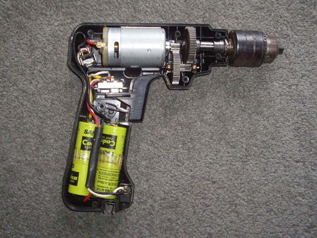
Figure 1. Black and Decker Drill Case Open
I disassembled the drill case and unsoldered the battery pack. Now is a good time to inspect the gear box and the brushes, give everything a good clean, and lubricate the gear box.
Then I unfolded the batteries into a plane just one battery high (reverse origami) before set about duplicating it using 3/4 Sub C NiCads with an increased capacity rating.
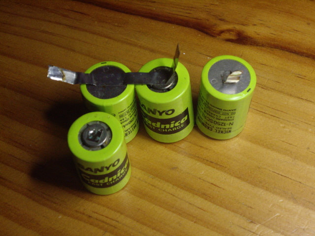
Figure 2. Reverse Origami
Before I can start welding the pack I need to develop welder and weld head parameters that will give consistently good welds. Using the dead NiCads and the offcuts from their nickel connections I set the welder voltage at 10 Volts with a 2 ms initial pulse and no weld pulse, with a weld pressure of 7 kg (15 lb). The nickel strips were tack welding with sparking. I increased the weld pressure to about 10 kg. No sparking but still tack welds. The initial pulse should clean the weld but not actually form a weld bead. I backed off the initial pulse progressively to 1 ms where there was consistently no weld.
I added a 2.5 ms delay and then an 8 ms weld pulse. No sparking but the welds were light and weak. I increased the welder voltage progressively to 12 Volts where there was minimal sparking and a secure weld with good weld bead formation. The nickel rips before the weld beads separate. The individual weld beads have an area of approximately nine times the originals, so the effective conduction area is about 30 times better than the original welds on these old batteries . This should be just fine for making the new packs.
The reason for welding battery tabs is worth a quick discussion. Soldering requires that the cell terminal is heated to about 350°C to form an effective joint. However the cell terminals have a large thermal mass which requires a relatively long heating process. This risks damaging the terminal insulation (which is usually a plastic disk) and adversely heating the cell chemistry. Welds apply a lot of energy - enough to fuse nickel and steel at above 1,450°C - but this is very localized at the terminal surface and very quick (tens of milliseconds). This prevents over-heating the cell terminals (you can immediately handle a pulse weld with no risk of getting burnt). The process is also much quicker than soldering in a production environment and provides a more secure physical connection than solder and capable of higher operating temperatures. For some cells soldering may also be difficult because of the terminal or tab material.
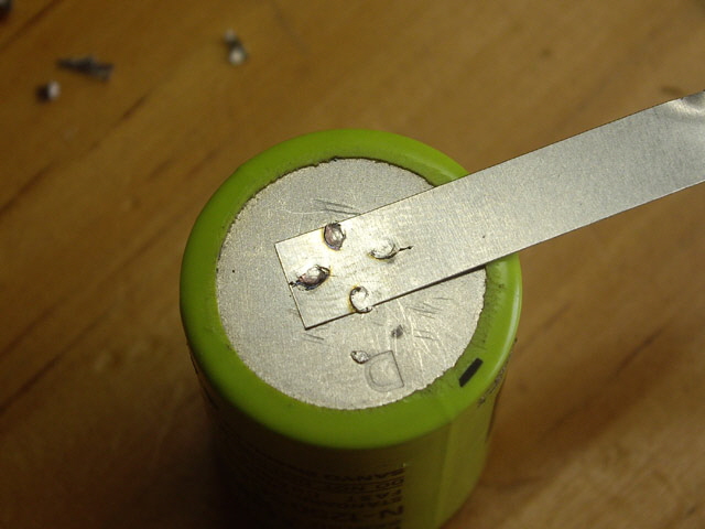
Figure 2. Good Welds on Dead Battery
(12 V, 1 ms, 2.5 ms, 10 ms)
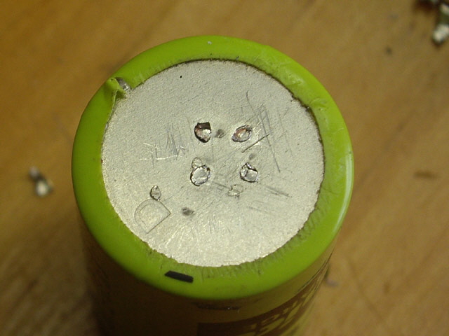
Figure 3. Ripped Tab to Inspect Weld Beads
(The new weld beads have a significantly greater area than the originals)
I made two or three weld pairs per battery tab connection. A rubber band was useful for keeping the batteries aligned. The welds were completed with a Perspex sheet on the Dremel press base to avoid shorting the cells, and using a piece of cardboard at the top to avoid inadvertent shorting cells through the weld head.
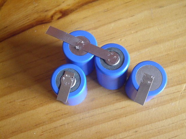
Figure 4. Rebuilt Pack
(Ready for folding, insulation and reconnection.)
With the pack connected together I measured the voltage at 4.8 Volts. That’s good and I probably haven’t damaged any cells with my welds. The welds look great and are more substantial than the originals.
The battery pack nickel tabs were soldered to the connecting cables and the drill was reassembled taking care to avoid pinching the wiring in the case.
The drill work immediately with plenty of torque, correct trigger action for half and full speed, and reverse.
I found the original charger (a wall cube rated at 6.5 V DC with a maximum current rating of 210 mA) and set the drill on charge for about 6 hours. While the battery was charging I replaced the original chuck (a long time lost) with a new one that I machined to fit the moulded chuck holder in the base of the handle. I also replaced the screw drive bit.
This drill is better than new with increased capacity NiCads and secure welds.
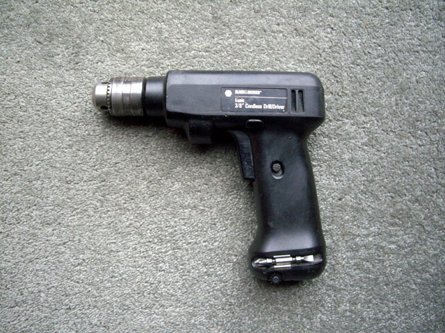
Figure 5. Refurbished Black and Decker Drill
The new weld head works well although it does creep forward about 2 mm during application of weld pressure. I have reduced this movement with a stotted steel seating washer on the Dremel shaft. While much improved there is still some slight forward movement of the electrodes at high pressures. Rather than remake the part I’ll be taking care when applying electrode pressure to make sure that the electrodes, tab and battery remain aligned. A permanent fix requires a more robust mounting bracket perhaps combined with reducing the electrode to Dremel press shaft distance.
The welds themselves are very secure and appear to be consistently formed. The weld cables jump a bit during the weld pulse, but there is minimal sparking and only occasional light sticking of the electrodes to the nickel tabs.
The weld head makes the welding process faster and more consistent than manual placement of the electrodes. The process is so controlled that I don’t involuntarily flinch or blink during the weld pulse.
The next pack was from a Hitachi 14.4 V portable drill. The pack was opened and inspected. The pack has a thermistor and what appears to be a thermal cut-out. The plug that connects to the drill base is a rather complicated affair of bent nickel sheets and I don’t want to remake this.
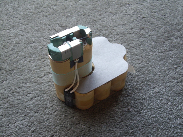
Figure 5. Hitachi Pack Disassembled
I photographed the pack to make sure that the rebuild would be essentially identical to the original. Then I desoldered the thermal trip, removed the cardboard insulation, and peeled the drill plug tabs from the old batteries. I plan on reconnecting these by sweat soldering to welded tabs because they will be difficult to access with my weld head.
The new batteries were welded together without any significant problems, again with two or three welds per tab connection using the original weld schedule.
During one weld an electrode slipped off the nickel tab just as the weld pulse was fired. This caused a considerable spark and some blackening on the top of the cell. I simply completed another weld adjacent to the first.
At some point in the weld process while I was adjusting stuff I received a moderate to nasty static electric shock. There is nothing in the welder that generates DC voltages above 28 Volts so I figure that the Dremel press has acquired a charged during the previous welds (the press frame is conductive but is insulated from the battery pack by a Perspex sheet forming a capacitor). The next weld was fine so I ignored this odd occurrence (much to my later regret).
The two vertically stacked cells were assembled separately and placed in their original cardboard sleeves, complete with the original plastic spacers. They were then welded to tabs already connected to the rest of the pack with the pack supported on some appropriately sized pieces of wood. The pack voltage measures 14.4 Volts.
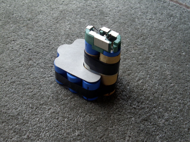
Figure 6. Rebuilt Hitachi Pack
With the pack welds completed the original plug conductors were sweat soldered to nickel tab terminations on the cells and the remaining sensor wire was soldered in place. During this process I did manage to inadvertently short the pack briefly through a set of pliers, but aside from some sparks there was no damage.
I secured the cells with electrical tape and replaced the original top and bottom cardboard insulators. Put everything back in the case and it’s good to go. The remade pack went straight into a 14.4 Volt charger.
The third pack was for a DeWalt 14.4 Volt hand drill The pack was disassembled (six case screws) and inspected. This will be easier to remake than the Hitachi pack because the plug arrangement is somewhat less complicated and one of the connections is soldered. The one complicating factor is a copper to battery welded connection. I’ll solder this to a nickel tab welded to the battery.
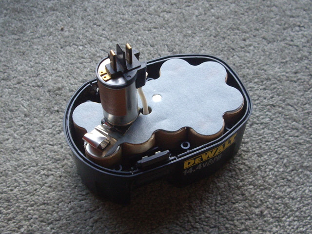
Figure 7. DeWalt Pack Disassembled
The nickel strips used in this pack are (with one exception) somewhat wider than my replacements. I don’t think that this will cause excessive voltage loss because the resistance of the new strips is already very low (about 0.0001 Ohms). The original welds appear to be quite substantial (similar in size to my 2.4 mm diameter electrodes) compared with the original Hitachi and the Black and Decker pack welds.
First I removed the copper tab from the battery plug by cutting through it with a razor blade driven with a small hammer. The tab came away cleanly.
The pack is essentially a single layer of cells with one stacked. I set about welding up the new pack. On one weld I inadvertently fired a weld that shorted across a nickel tab to the back of the negative electrode holder. No damage was done other than some weld marks on the edge of the nickel tab at the point of inadvertent contact.
Just over half way through the job a weld went ‘splat’. This was definitely different from my usual welds which are best described as a ‘clunk’ from the jumping weld cables. It suggests inadequate weld pressure, perhaps a dirty electrode tip which causes sparking, and perhaps too much weld energy. I cleaned the electrodes, checked the welder settings and tried to make a second weld. Splat! These welds have way too much energy.
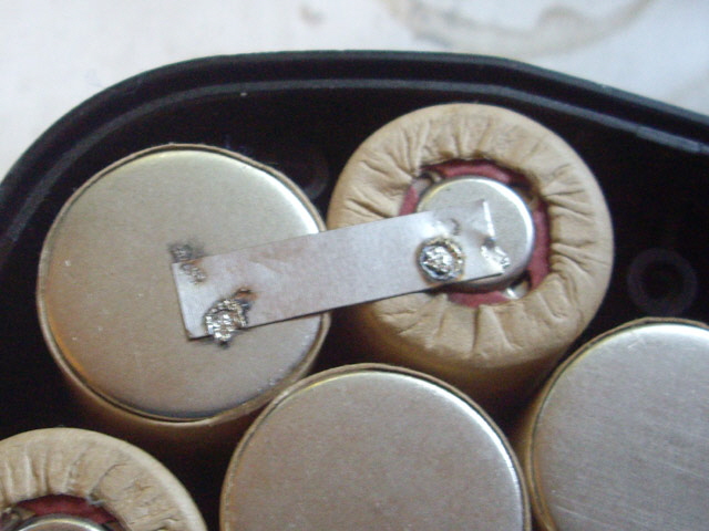
Figure 8. Two Splat Welds! Oops - Something isn’t Right
I immediately reverted to some old batteries. Something odd is going on and I don’t want to damage the partially rebuilt pack any further. As an aside the cell voltage is still fine so these welds haven’t damaged anything other than the tab - a cosmetic defect that will not be visible.
I reset the welder (power off and on). Everything their looks good and appears to be fully functional. I checked the pack to make sure that the nickel tabs were all correctly aligned and that I was not trying to do something dumb like weld a dead short across the cells.
I checked out the weld cables and found one problem. The negative cable termination at the welder had worked loose as a consequence of inadequate tightening combined with cable jumping during the welds. I remade the termination.
With everything looking okay I tried another weld. The trigger fired but there was no weld at all? I tried a few more times with the same result. It was time to think carefully about what was going on.
The microcontroller, LCD display, front panel controls, trigger and trigger detect are all fully functional.
The capacitors are charging and discharging under front panel control. The charge time is indicative of the capacitance which remains at about 3 F. So the charge and discharge boards are working and the capacitors are good.
The power supplies are all working (the discharge board 12 volt supply also powers the cooling fan and this is working fine, the microcontroller is working and the capacitors are clearly charging).
The temperature sensors are working and nothing is getting hot (everything remains at about 24°C).
The welder cables and weld head are good with good terminations and a highly conductive path to the weld junction. And the electrode tips are clean.
I have just completed about 200 welds (including setting up the weld schedules) largely without incident. The last two weld splats suggest either excessive discharge time or insufficient weld pressure.
The main MOSFET switch does not appear to be firing or, if it is, it is not delivering appreciable current to the weld. This suggests that that either the gate driver has failed, a MOSFET has developed a short between the gate and source, or all of the MOSFETs have failed. The only way to sort this out is to remove the MOSFET switch, check the MOSFETs and measure the performance of the gate driver board. Time to take the new case lid off and start taking some measurements.
On removing the switch bus I found another loose and dirty termination problem. The bolts that secure the copper bus to the capacitors were just finger tight and the bus itself had turned dark brown through significantly surface oxidation. The surface oxide forms over time where the bus is exposed to air. Its formation is enhanced by finger prints and handling - and this part of the bus was subjected to a lot of handling during fitting of the case. While this could account for low delivered current to the weld junction we have just completed a whole bunch of successful welds.
I do love my bus design. With the bus structure unbolted (19 machine screws) I can test each MOSFET individually. Desoldering all these MOSFETS without actually causing more damage than you’re trying to fix could be a challenge.
With the MOSFET switch and bus removed there are no obvious signs of damage. Ohm meter checks show that the gate resistance is high, and that there are no bus shorts. I disassembled the bus and checked each MOSFET individually. The body diodes are all okay. The MOSFETS all switch on and off within 200 ns. The RDSon was typically 2.5 milliOhms (0.0025 Ohms). So the MOSFETs appear to be completely serviceable.
The inside of the bus structure that makes contact with the individual MOSFET leads was perfectly clean. The bus was originally assembled with clean copper while wearing disposable gloves.
The free wheeling diode diode was checked. This is open circuit (dead). There are just two conceivable failure modes. Excessive reverse voltage (the rated reverse voltage is just 100 Volts) or over-current (more than 12,800 A for more than 3 us).
I measured the MOSFET switch gate drive with a parallel capacitive and resistive load. It is operating perfectly under control of the microprocessor. The gate drive is normally actively driven off and there is a 125 us software delay in switching to prevent driver MOSFET cross conduction.
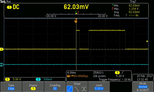
Figure 9. The Gate Drive (Yellow Trace)
There is no obvious reason for the weld failure here. The gate drive is functional and the switching MOSFETs are functional. The fly back diode is open circuit but this would not have inhibited the discharge. There were no shorts on the copper bus. It is worth noting that this welder has made thousands of welds over time, including some very high current discharges around 10,000 Amps and into a dead short with deliberately coiled weld cables around a shorted turn (an extreme test of welder stability).
The loose negative weld lead termination was clearly a problem but not sufficient to prevent the previous 200 welds. I suspect that when I tightened this I disturbed the poor connections on this bus. This may have resulted in limited discharge current giving the impression of the MOSFET switch not firing.
The damaged free wheeling Schottky diode was almost certainly caused by a reverse voltage static discharge similar to the static shock that I got during the Hitachi pack rebuild. The diode needs to be replaced before I can get back to welding or I will risk damaging the MOSFETs.
The only conductive item on the bench that is not connected to ground is the Dremel press base plate. This is aluminium, insulated from the battery pack by a piece of Perspex (a good insulator with a dielectric constant similar to Mylar). I figure that consecutive weld pulses are charging the Dremel press plate although I have yet to figure out the exact mechanism. It may be relevant that the MOSFET switch is not a bipolar device (weld discharge pulses involve only electrons for N channel devices). The only thing that is different about the current set up is the weld head, the numerous sequential welds, and the static shock that I experienced.
The ‘splat’ welds were almost certainly caused by excessive weld time. With a dead free wheeling Schottky diode the MOSFETs were probably going into avalanche resulting in an extended duration weld.
In order to prevent the problem from recurring I’ll be grounding the Dremel press so that any induced static charge cannot accumulate. I have some 15,000 A 70 Volt transils in a box somewhere that I never quite got around to fitting. I’m going to be placing one of these directly across free wheeling diode and another directly across the MOSFETs (drain to source) to protect them from static discharges and transients. And I’m going to be reassembling the MOSFET switch and the buses with clean copper and properly tensioned fasteners.
A new Schottky diode is on order.
In the interim I’ll be making some holes for fitting the transils, cleaning the buses back to shiny copper (no time for silver plating at the moment but I really should be doing this) reassembling the MOSFET switch, and re-installing everything back in the case. While I’ve got the switch in pieces I’ll also going to improve the case mounting. The four through-bolts on the switch mount are the only remaining ‘difficult to access and assemble’ fixings in the welder.
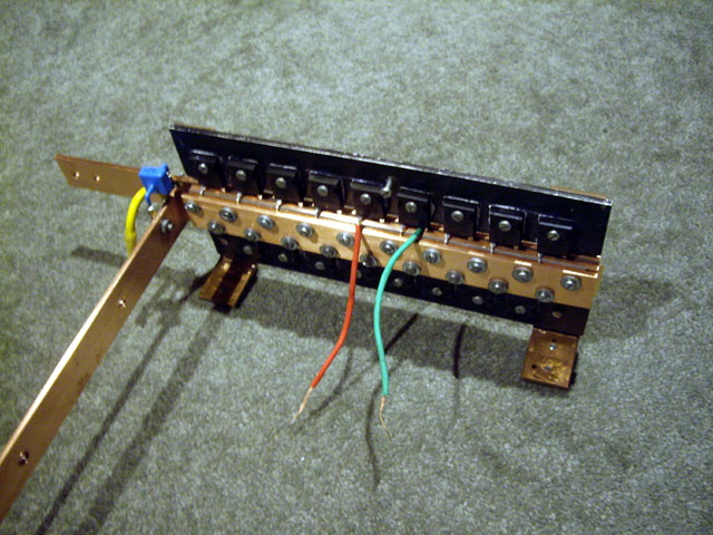
Figure 10. MOSFET Switch Reassembled with Clean Copper and New Transil
(The blue transil is mounted directly across the MOSFET switch.)
I’ve been thinking about that nasty static discharge (it was real - I felt it) and propose the following mechanism for its appearance.
The first step in a weld is to attach the electrodes to the job. This grounds the top of the Perspex plate. Any charge on the Dremel base plate adjusts to the applied potential.
The weld pulse occurs. This involves a large number of electrons (6.2 x 10E18 x current) so the top of the Perspex plate becomes positively polarized and the bottom negatively polarised (typical dielectric charge separation).
Electrons are free to move in the metal base plate and (a leap of faith here) some combine with the holes (+ve charges) on the underside of the Perspex. The Dremel base plate has therefore acquired an induced negative charge.
The Dremel base plate is insulated and the weld pulses are relatively frequent so there is minimal leakage to ground.
The cycle is repetitive so with each weld the base plate (in effect one plate of a small value capacitor) becomes increasingly negative.
Eventually the Dremel base voltage becomes sufficiently high (and negative) to discharge through a relatively low impedance path to ground.
If this discharge path is to the positive welder electrode then it is to ground (real earth ground) and nothing adverse occurs. If it is through the operator then they feel a mild to moderate static electric shock. If it is to the negative welder electrode then it is applied reverse biased across the Schottky diode and to the drain terminal of the MOSFET switch.
The specified minimum drain to source breakdown voltage rating of the MOSFETs is 75 Volts. The specified maximum reverse voltage of the diode is 100 V. I figure that the combined physical proximity to the static source and path to ground through the diode is significantly less than through the MOSFET switch. Hence a static discharge to the negative welder terminal will kill the protection diode.
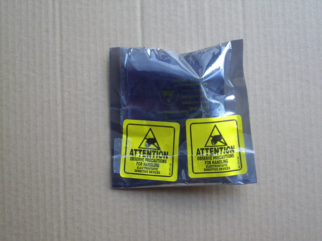
Figure 11. New Diode in Anti-Static Packaging
(Yes, the device is clearly susceptible to static damage.)
Inspection of dead diode revealed two weld marks on its base. This suggests that the failure mechanism included a cathode to anode short circuit at some stage. The resulting current pulse would have destroyed the forward junction and caused the weld.
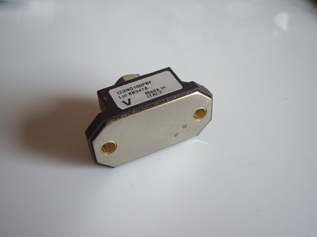
Figure 12. Weld Marks on Base of Schottky Diode (Lower Right)
The 70V (maximum) 15,000 A transils should protect both the MOSFET switch and diode from future damage due to static and provide a further level of protection from weld transients. I should have fitted these years ago! While a second transil is not actually required this provides a belts and braces protection design. If the the Schottky diode ever fails again this should prevent the MOSFETs from going into avalanche.
I’m waiting on the new diode before I can put everything back together. If the new diode isn’t here in the next couple of days I’ll probably be getting around to selective silver plating of parts of the bus structure. As an aside I found the parts that I silver plated several years ago. They are still as bright and shiny as the day they were plated.
It appears that my diode is on back order. I contacted another supplier and ordered another diode. It was here (all the way from Hong Kong) in just four days. Eventually I will have a spare. I’ve started re-cleaning the last of the bus structure and have decided to replace the fasteners and star compression washers. Unfortunately I don’t have enough in stock to finish reassembly. The welder should be back up and running tomorrow.
With the diode replaced, the transils installed, and everything reassembled the Dremel press base was grounded. This is a simple wire connection to the positive weld terminal which is permanently connected to earth. This is one of the advantages of my bus and switch design. Effectively both welder electrodes and the job are connected to ground before the weld. This also means that there is no requirement for high-side MOSFET switching.
The welder was back in operation without splats. Securing the bus structure with clean tight terminations means I need to revisit my weld schedules. I ended up with 12 V, 0.6 ms Pulse 1, 2.5 ms Dwell, 16 ms Pulse 2 with a pressure of about 15 kg (2/3 stroke). The reason for the increased Pulse 2 is that I have increased the electrode length to prevent accidental cell shorts and make positioning easier.
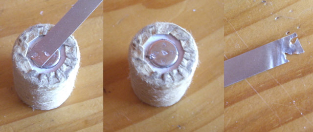
Figure 13. New Weld Schedule After Rebuild
(12 V, 0.6 ms Pulse 1, 2.5 ms Dwell, 16 ms Pulse 2, 15 kg)
In completing the DeWalt battery pack I only made a single bad weld. One electrode was positioned on the nickel tab but off the cell (and therefore had almost no applied pressure). The resulting low pressure weld burned a hole clean through the tab. Although I need an electroscope to measure static charge (and I don’t happen to have one) there were no more static shocks during these welds.
Click here to see a video of making a battery tab weld.
With the DeWalt pack reassembled the pack voltage was measured 14.8 V DC and the drill is back to producing significant torque. The new pack was fully charged in less than an hour. I have another of these DeWalt packs and four other brands to rebuild. I don’t expect any more hassles with this process.
Job done.
If you have a failed NiCad or Lithium Ion battery pack that you can’t replace or where a replacement is more than the cost of a new tool then chances are I can rebuild the pack for you - often using higher quality and capacity cells than the OEM product. Feel free to contact me for an obligation free quote.
|