|
The Elegoo Saturn 2 has about 1.2 mm of axial play on the Z axis lead screw caused by the stepper motor thrust washer and the resilient stepper motor mount.
Note that this is a lead screw as opposed to a ball screw and I’ve only recently been corrected on this. The lead screw nut incorporates spring loaded anti-backlash which is effective.
Video 1. Lead Screw Axial Play Measurement
(Click on the image to view on YouTube.)
You can see from the following video that there is little, if any, backlash.
Video 2. Lead Screw Backlash Measurement
(Click on the image to view on YouTube.)
The axial play in combination with initial layer compression results in dimensional inaccuracy over approximately the first 2.5 mm of the model, and a reduction in the Z height of the finished model of about 0.8 mm including resin shrinkage.
Figure 1. Saturn 2 Performance out of the Box
What on earth is happening with the blue plot? Here is my understanding. The very first layer is being printed way too thick. This is caused, at least in part, by the hydraulic force of trying to squish the very first layer of resin to 0.05 mm. The path of least resistance is to push the entire lead screw and Z motor upward.
The subsequent layers are forced to be too thin (less that 0.05 mm) by the thick initial layer. This continues for about 20 layers until the hydraulic force required to form an 0.05 mm layer equals the axial play lift.
As a consequence the printed part ends up compressed by about 0.8 mm in just the first 40 or so print layers. The effect is probably more pronounced with larger models. The effect is known by the misnomer initial layers compression when it is actually caused by the very first layer being too thick.
If we can stop the lead screw axial play then the printed part should have layer heights approaching ideal.
A short note on my standard calibration model for Z height. It is essentially a scissor stair with a tread depth of 0.1 mm to a maximum height of 3 mm. It is large enough for convenient measurement with calibrated instruments to within +/- 0.01 mm, but small enough to save resin. Measurements are repeatable.
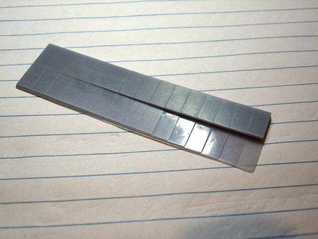
Figure 2. Calibration Print
For models on rafts and supports and for artistic models initial layers compression is unlikely to be a concern. But for engineering models sitting on the build plate, particularly with critical Z dimensions or important detail in the first few millimetres, it can be a significant problem.
There are a number of fixes for the issue including model compensation, reworking the Z stepper motor, and building on rafts and supports. But these all cause other problems including having to adjust every model for a particular printer, increased motor and lead screw wear and noise, and having to rework support points and surfaces at low inclined angles to the build plate.
A link that discusses the issue can be found at the link reworking the Z motor. While the link does not refer to a Saturn 2 the problem is identical.
My solution is different. I have installed custom-made thrust bearings at the top and bottom of the lead screw between the Saturn 2 cast aluminium deck and the top of the Z column extrusion. It works, it is easy to install (the covers don’t need to come off the machine), and no additional load is placed on the Z motor. The only drawback that I’m aware of is a reduction of about 8 mm in the maximum build height.
Construction was remarkably straight forward with just five machined parts, six cap head machine screws, six set screws, and 26 x 1/8th inch steel ball bearings.
Each bearing comprises a boss that is fixed to the ball screw by three brass set screws and a seated bushing. The existing plastic plate at the top of the Z axis extruded column is replaced with a 7.8 mm thick aluminium plate.
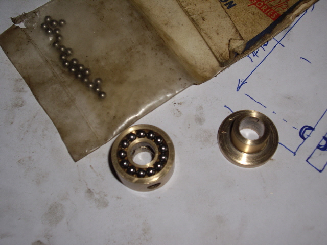
Figure 3. Upper Bearing
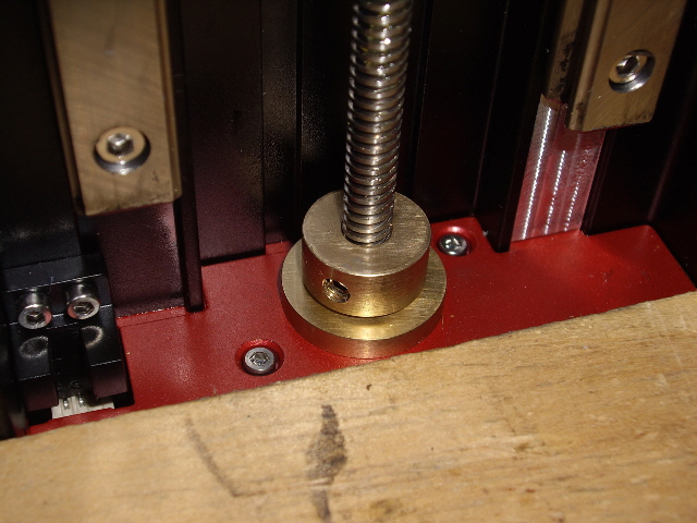
Figure 4. Lower Bearing
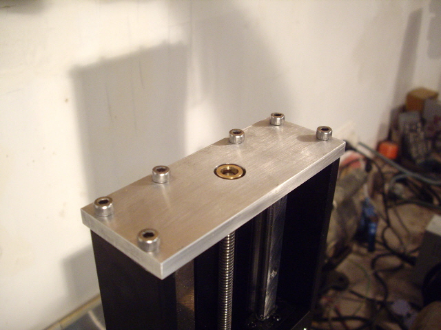
Figure 5. Top Plate
There were a few iterations as the design developed. My original bearings did not incorporate steel ball bearings. But from time-to-time the bushing would begin to turn with the lead screw causing an unpleasant noise. The problem was that the bearing area between the brass bushing and boss was greater than the bearing area between the bushings and the case/ top plate.
There were a few tricksy (yes, a real word thank you Gollum) bits.
- The first was getting the cap screw holes exactly on centres in the Z column extrusion. I used bearing blue to get a reasonable copy of the extrusion profile and confirmed dimensions using 4 mm drill bits inserted into the extrusion holes. I drill the holes with a CNC mill on a piece of 1.2 mm thick aluminium sheet to ensure they were sufficiently accurate before finally drilling the aluminium plate.
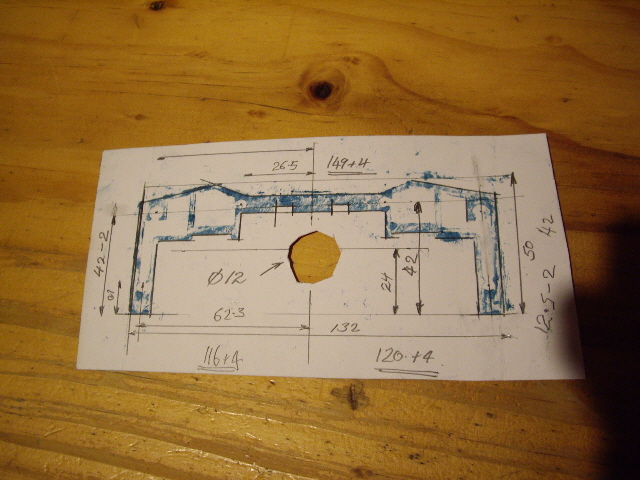
Figure 6. Print of Z Column Extrusion
Video 3. Machining the Top Plate
(Click on the image to view on YouTube.)
- The second problem was how to hand-tap the Z column extrusion holes to M5 - 0.8 without the tap wandering off vertical due to the open sides of the extruded holes. I used the aluminium plate with 5 mm diameter holes as a tap guide. Then I over drilled the 5 mm holes to 5.2 mm for the cap screws.
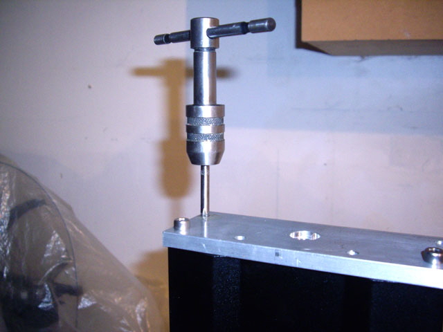
Figure 7. Taping the Extrusion using the Top Plate as a Guide
- I had to spend some time making a tool to turn the bearing race. Thankfully I have a collection of broken carbide 1/8” drill stubs from drilling Printed Circuit Boards (PCBs). These were perfect with some hand grinding and an appropriately designed tool holder.
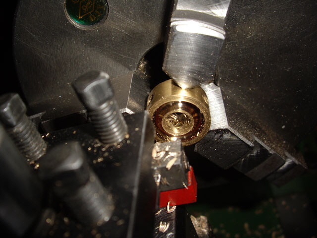
Figure 8. Turning the Ball Race
- The original cap screws are too short for anything but a cosmetic cover. I’ve replaced them with 16 mm M5 - 0.8 cap screws, but 18 mm would be better. This should ensure that the female threads in the extrusion won’t strip provided that they are not over-torqued.
Fitting
Fitting the modification was straight forward with no need to open the covers on the Saturn 2. The modification is readily removed in about 15 minutes, but after you’ve applied it and seen the improvement you’ll never want to go back to the original build.
- Remove the vat and the build plate. Place a piece of MDF or clean plywood over the LCD to protect it from tools or dropped parts.
- Remove the two M5 - 0.8 cap screws from the plastic top cover and remove the cover.
- Fit the new plate using two M5 - 0.8 16 mm cap screws and align the extrusion holes using the shank of a 4 mm drill bit.
- Tap the threads by hand to a depth of at least 12 mm using the 5 mm holes in the plate to keep the tap perpendicular to the top of the Z column. Use cutting fluid or regular machine oil. Progress slowly, one turn forward then ½ a turn back.
- Drill out the four 5 mm holes (used at the tap guides) in the top plate to 5.3 mm on a drill press and if necessary deburr.
- Undo the two hex screws that fix the lead screw nut to the Z arm. The Z arm will drop, guided by the rails. Turn the Saturn 2 on and drive the nut up and off the lead screw using the touch screen. Then turn the Saturn 2 off.
- Put the lower bushing and boss together retaining the ball bearings, and slide down the lead screw, seating in the circular recess in the deck. Pressing gently downward tighten the three M5 x 0.8 set screws in the boss onto the lead screw. Rotate the lead screw by hand to access all three set screws.
- Turn on the Saturn 2. Refit the lead screw nut and use the touch LCD to drive it down. Then turn the Saturn 2 off.
- Put the upper bushing and boss together retaining the ball bearings, and slide down the lead screw.
- Fit the top plate using the six 18 mm long M5 x 0.8 cap screws to finger tight and unscrew ¼ turn. This allows for ~0.2 mm preload on the thrust bearings.
- Slide the top boss up to engage the bushing with the hole in the top plate. Note that the excessive radial clearance between the hole and the bushing is deliberate to allow the top of the lead screw +/- 1.5 mm play.
- Pressing gently upwards tighten the three M5 - 0.8 set screws in the upper boss onto the lead screw. Turn the lead screw by hand to access all three set screws.
- Tighten the six M5 - 0.8 mm cap screws on the top plate.
- Confirm that the Z axis moves freely up and down from the touch LCD with no noise and that the bushings do not rotate with the lead screw.
Does it Work?
The modification has significantly improved the performance of my Saturn 2 without having to mess with the stepper motor or resilient mount. If anything the machine is quieter than before the modification.
With the parts fitted I measured the axial play. It has reduced from +0.3 / -0.9 mm to less than +/-0.1 mm under a load of about 500N (about at much force as I can apply with the fingers of two hands).
Much of the residual movement appears to be due to the carriages rocking on the linear rails. The modification has eliminated axial play to the physical limits of the Saturn 2 rigidity, but it hasn’t eliminated all sources of build plate defection.

Video 4. Reduced Lead Screw Axial Play
(Click on the image to view on YouTube.)
My calibration prints have improved from being -0.8 mm lower than the design height at 3 mm to -0.20 mm. This -0.2 mm below ideal is due almost entirely to resin shrinkage. Shrinkage is listed in resin manufacturers’ data sheets and is typically up to 6% in Z. So the modification has eliminated axial play in the ball screw.
Layer height linearity (slope) is good from about 0.5 mm whereas linear layer height used to start from a design height of about 2.5 mm.
But we still have a very first layer that is about 0.22 mm too thick (reduced but not eliminated). And this is still being caused by the hydraulic force the resin exerts against the build plate during first layer compression. But there is a solution to this too. Click here to read about my quest for perfect first layer height.
Figure 9. Axial Play Removed with Significantly Improved Performance
Is there a Kitset?
Some folk have asked if I’ll make a kitset for this modification. I’d like to, but I need enough interest to distribute tooling costs otherwise a kitset will be too expensive. If there aren’t enough takers then I will post the drawings and specifications for all of the parts here (once I’ve drawn them up).
If you’re interested you should first consider the need to tap the existing holes on the top of the Z column extrusion (I can’t do this for you) and over-drill the 5 mm diameter guide holes in the top plate to 5.3 mm. These operations can be carried out with simple hand tools.
Please contact me to register your interest in a kitset.
There isn’t enough interest for me to make a kitset. Limited numbers makes the parts too expensive to make or have manufactured. But I have designed and tested SLA 3D printed bosses and bushing that house a commercial miniature thrust bearings (8 x 16 x 5 mm) so that you can eliminate axial play on your Saturn 2.
Here’s how well the SLA 3D printed thrust bearings performed. Every printed layer and the cumulative height of all layers are within 2 thousandths of an inch of the design.
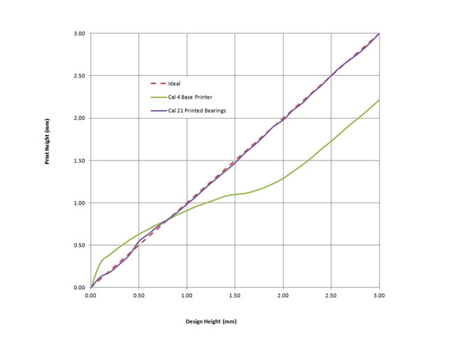
Figure 10. Actual Verses Modeled Print Height
(with SLA 3D Printed Bearing Housings)
I have modified the boss design to include a female lead screw thread that engages with the Z Axis ball screw. This reduces the duty on the three M5 brass set screws which now primarily prevent rotation of the boss on the ball screw. The boss internal thread provides a bearing area of approximately 63 sq mm that resists the axial play. If you have ever trodden on a Lego brick you’ll appreciate how strong plastic parts can be under compression.
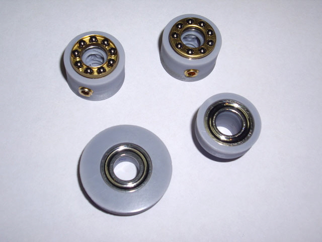
Figure 11. New SLA Printed Bearings
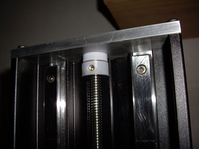
Figure 12. Upper Printed Bearing Fitted
If you’d like the STL files for the boss and bushings please contact me. The boss lead screw thread is deliberately a close fit on the Z axis so you may need to scale the model fractionally to achieve this depending on your resin and the performance and condition of your printer. All threads are incorporated in the models and should not require post-print machining.
I have also attached a plan for the replacement top plate to be fabricated from about 7.8 mm thick aluminium rectangular bar. The 14.3 mm wide central flange slot can be replaced with a 15 mm diameter hole to ease machining. The 5 mm diameter holes need to be over drilled to 5.3 mm after they have been used as a tapping guide for the Z column aluminium extrusion. The holes need to be machined within +/- 0.10 mm of centres to ensure unforced assembly. All sharp edges and corners should be broken by a chamfer or fillet (there is no need to bleed here). Note that a printed top plate isn’t an option as it would need significant web reinforcement to provide a fraction of the stiffness of the aluminium plate.
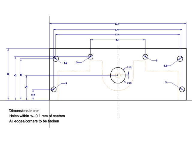
Figure 13. Aluminium Plate
Aside from the top plate you’ll need to purchase:
six M5 – 0.8 x 5 mm brass set screws,
two 8 mm ID x 16 mm OD x 5 mm thick miniature thrust bearings, and
six stainless steel M5 – 0.8 x 18 mm hex cap screws.
You’ll either need to machine or 3D print two bosses, and the top and bottom flanges. Contact me for the STL models for the 3D printed parts. Click on the following links to download the STL models.
Click on First Layer Quest to link to another page on the Saturn 2.
|