|
The machine base and spider were partially assembled with the Z motor, lead screw guides, linear bearings and some stops installed. I checked the pre-assembled component fasteners and they were all secure.
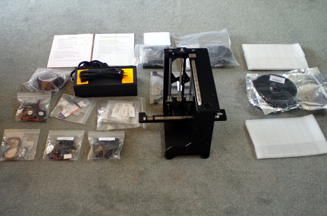
The first step was to unpack all of the parts from the styrene chips and spread them out so I could find stuff. In the numerous plastic bags you will find a set of tools and some lithium grease. You will also need some side cutters, a set of veneer callipers (but a rule will do at a pinch), and a set of small metric open ended spanners (I don’t recommend using pliers even though the instructions suggest that these can be used). You will also need some 3-in-1 oil (lubricate, penetrate and protect) at the end of the assembly process.

Figure 1. Laying Stuff Out
The very next step was to clean the partially assembled base with a vacuum cleaner because small bits of Styrofoam were in all sorts of awkward places.
Then I headed to the MakerGear Web site and downloaded the assembly instructions, the assembly exploded diagrams and the wiring instructions. The kit comes with an SD Card loaded with three trial models. MakerGear might consider installing the PDF documentation on the SD Card to save you some time and ensure that you have the appropriate version of the everything you need right out of the box.
Okay – time to follow the assembly instructions. These are not perfect and some of the photographs are not as informative as they might be. While there was nothing that I could not resolve, there is, in my opinion, scope for improvement. I suspect that who ever wrote these instructions has assembled a few of these machines and as a consequence has missed stuff that the first time constructor might want to know. Here are a few comments that you (and MakerGear) might find helpful. The following comments 1 to 7 refer o the M2_Assembly110913.pdf assembly instructions.
Page 4. The L shaped corner brackets that mount the heated flat bed plate to the spider have no stop for the machine screw heads. If you keep tightening the screws they will sink into the corner brackets and distort them. So how tight do you fit them? I positioned them with the bottom of the head finger tight to the upper surface of the L bracket.
A quick note in the instructions on tensioning machine screws would be useful. In general tighten to first resistance and then an extra eighth turn. When a part is fitted with several machine screws tighten them progressively from finger tight to keep mating surfaces flat. If stuff starts to distort or flex then you are too tight or missing a washer or spacer.
Page 5. There are no countersunk M3 x 16 machine screws in the kit. The associated exploded drawing shows a chamfer headed M3 x 16 flat headed machine screw. I used a cap headed screw instead.
Page 6. How tight do you tighten the machine screws for the spider levelling assembly? The instructions say ‘Tighten screws.’ If the screws bottom out against the spacers then there is essentially no point in having the springs. I fitted them finger tight to the spacer (with the springs fully compressed). They will be adjusted later during bed levelling so don’t over-tighten them.
Page 8. The M6 nut is not required for assembling the idler roller sub-assembly, but it is for fitting. Note that you will need two of these so you should assemble them both at the same time. They are identical.
Page 12. The parts list calls for 4 M2 washers. These are not shown in the exploded drawings or photos for attaching the 630 mm X belt to the extruder mount.
Page 38 shows the mounting of the case to the frame. This is a silly arrangement. Why not mount the case base to the frame using the Nylon machine screws that also act as RAMBo mounts? This wound be more secure than the current arrangement, ensure adequate side clearance for cooling, and save a bunch of fasteners and washers.
At the end of the assembly you will still have a bunch of unassembled parts including the fan sub-assembly, the X stop, the Z stop clamp and the Z limit bolt, a cable cover (which is also a filament guide). You will also have a collection of unused nuts and bolts, some of which will be required during the wiring assembly. Your parts list advises that ‘Extras of most fasteners are included.’
Refer to the exploded diagrams and fit the fan sub-assembly to the extruder housing. There are no instructions for this but the fans need to be fitted for wiring.
Aside from all of the extra bits, you are now about a third of the way through the process. If you are following the instructions then you will now need to progress to the wiring assembly instructions. The following comments refer to the M2_Wiring110913.pdf wiring assembly instructions.
The X, Y, Z and extruder motor pug polarity (red wire to rear) as described in the wiring instructions contradicts the instructions in the RAMBo manual (red wire to front). These plugs are not polarized. If they are wrong then your motor will drive in the wrong direction. but it will still work. The installation instructions with the red wire to the rear work correctly.
Page 10. There are two extra large cable-ties in a separate bag from all of the small ones for attaching the cable looms to the X and Y motors. You don’t need to join two smaller cable ties together if you look for the larger ties – they are there somewhere.
Page 11. There is an extra cable-tie on the pre-assembled extruder loom that won’t fit into the clamp on the top of the extruder housing. I cut it off.
Page 12. The photo shows that the Z manual adjustment knob is already fitted but there has been no instruction so far to this effect. The Z adjustment knob has a grub screw already inserted. The screw is not shown on the exploded drawing set. You will need to use the 2.5 mm hex key to tighten it. If you position the knob slightly above the frame then you will avoid friction and wear but depending on where the grub screw makes contact the knob may be tilted slightly off centre. A simple nylon spacer would be a useful kit addition to fix this. I have inserted an appropriately sized steel washer until I can get around to making a nylon spacer.
Note that the fans that you have been provided with may not be identical to the parts shown in the exploded drawings. This is a bother because my 50 mm fan mount has no effective spacer in its frame and, with just a single mounting bolt, the fan frame deflects when there is sufficient tension to stop the fan flopping about.
In my opinion the fan mounting is a significant weakness in the current design. I will be making something that is positive positioning and more robust in due course (but maybe I need an operating printer for this exercise).
Page 18. The Z stop will not fit securely to the rear guide rail. I sanded down the 3D printed clamp mating surface about 0.2 mm and this has fixed the problem.
Page 24. The additional sleeving provided for the heated bed wiring was much longer than shown in the photograph with the potential of restricting free movement of the X axis travel. I trimmed it to what appeared to a sensible length (about 100 mm) with a pair of scissors.
Page 29. My SD Card cable loom was not white with a polarity indicator as shown in the assembly instructions, but fully colour-coded. After searching around the Interweb I eventually found that the red wire is + 5 Volts and should be connected as for the polarity indicated white wire.
When trying to fit the RAMBo case lid it became apparent that one of the board connector profiles has changed resulting in insufficient clearance between the connector and one of the fan mounting bolts on the lid. Either disobey the instructions and gently force the fit (it will fit without breaking or visually distorting stuff) or dispense with the obstructing fan mounting bolt.
There is no positive locking of the RAMBo case lid. Mine sits there under the upward pressure of the cable looms. I’ll be fitting a 2 mm diameter machine screw in due course to keep the lid in place.
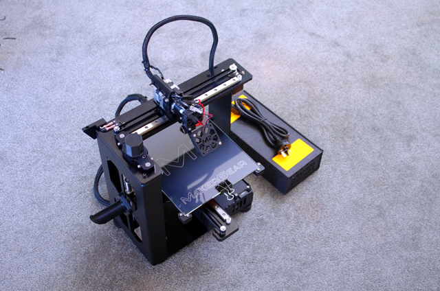
So everything is now assembled and your will still have a bunch of nuts, bolts and small cable ties left over. Before you do anything else I recommend that you adjust the Z stop bolt to activate the associated micro switch when the heated platform is about 5 mm away from the extruder head. Although the table has not been levelled and Z stop will be set eventually, this crude manual adjustment will reduce the possibility of driving platform into the extruder nozzle.

Figure 2. Assembled
(Note that the extruder motor and fan wiring harness has yet to be fully
secured to the extruder head with cable ties.)
Now is also a good time to lubricate the linear bearings and the Z axis lead screw with the lithium grease provided, and the Z axis guide rods and the idler pulleys with 3-in-1 oil. A little bit of grease or oil will go a long way.
- Use a dot of lithium grease on each Vee of the linear bearings and four dots on the Z axis lead screw. Work the X, Y and Z drives to spread the grease. Wipe off the old grease when re-lubricating after each 10 hours of printing.
Okay we have an assembled machine. However it won’t be doing anything until you download and install an interface program and the drivers for the RAMBo USB port. My computers are primarily Windows based and the download and install instructions were relatively straight forward. By the end of the installation process you will have applied power to your M2 for the first time.
Continuing following through the first time user instructions to progressively check that each component is working, operating in the correct direction, and progressively setting end stops and leveling the bed.
Note that the only part that you won’t explicitly test at the end of the installation process is the SD Card reader. This is actually read by the Proterface software interface and as there were no reported errors I figure it is working. The final test will come when I try and print from the card.
I couldn’t find any explicit instructions for threading the filament and filament guide tube prior to the extruder test. (They exist in the document M2_-_Setting_Up_Your_M2.pdf). The filament spool unwinds counter-clockwise when looking at the left hand side of the machine and the filament passes through a hole in the ‘X End Wire Stop Shroud’ (see page17 of the wiring instructions), then through the clear plastic filament guide tube directly to the top of the extruder housing.
It would be nice if the extruder housing had a recess to receive the filament guide tube. I might drill it out to 5 mm to a depth of say 3 mm at some time in the future.
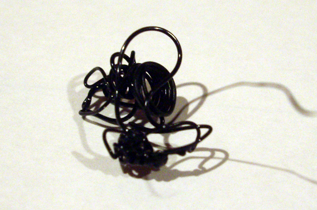
With the assembly and testing completed you now have a working machine and you will also have completed your first 3D print in testing the extruder – in my case a small squiggly blob of PLA. Let’s call it modern art - I have seen worse!

Figure 3. My First Print (PLA blob from the extruder test)
With the M2 all set to go it was time to remove it from the dining table and find a place to set it up. My initial thought was to put it in my office but the machine is actually quite loud in operation and requires a sturdy base to reduce vibration (particularly at the end of a fast Y traverse). This forced me to have a thorough cleanup of my workshop which, with an interlude to clean up some tools, which took the best the a day. The printer has now found a home on a sturdy stainless steel topped bench. I will be making a plastic cover for it to protect it from errant dust.
Click here to navigate to stuff to print...
|