|
Apparently there are some rules for metal casting. I would prefer to call them Laws which allows for interpretation, but in any case I am in clear violation as my casting is somewhat short of perfect.
In viewing the following images please bare in mind that this casting is just 80 mm long (the maximum dimension shown in Figure 1) so most of the images are twice full size and many are at much higher magnifications. The basic surface is surprisingly flat with a smooth surface ripple less than 0.2 mm deep.
Defects and Causes
Note that references to top and bottom are relative to the position of the ingot pattern as cast.
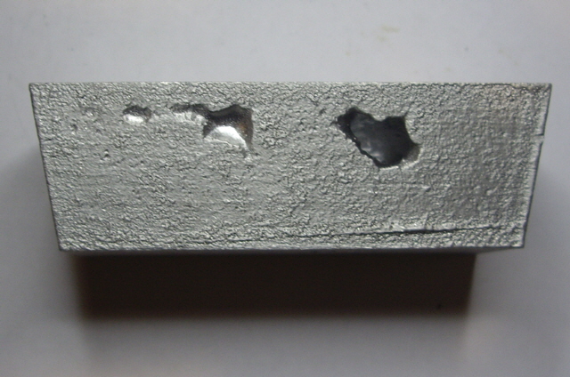
Figure 1. Major Void, Minor Sink and Line
There was one major void in one side and some minor sink on the bottom and sides of the casting. These all had smooth shiny surfaces. There was also a line caused by my careless removal of the pattern.
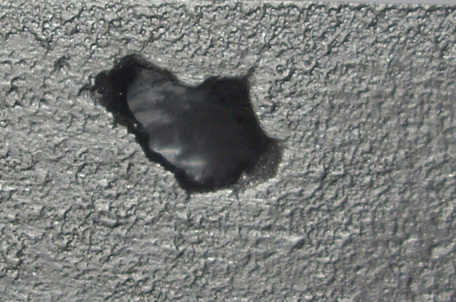
Figure 2. Close-up of Major Void (Note shiny interior)
The text reproduction was poor but this was immediately apparent when the pattern was removed from the mould with sand in the text recesses. I put this down to a number of causes: detail too fine, inadequate draft, poor pattern surface finish, inadequate parting application in the text recesses, and perhaps inadequate sand ramming.
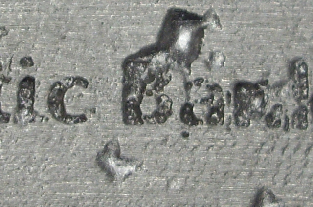
Figure 3. Text with Occlusions Minor Sink
There are a few minor surface inclusions at the top of the casting (one or two grains of sand embedded in the surface).
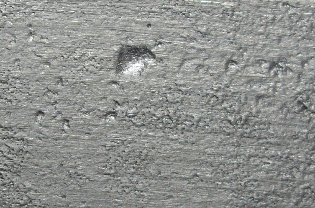
Figure 4. Top of Casting with Sand Grain Occlusions and Minor Sink
The surface finish was surprisingly good given my concerns about the green sand grain size. The 3D print layer lines were clearly discernible. The bottom of the casting was dead flat but the casting top of the casting had very minor smooth irregularity and a slight warp. I put this down to uneven and possibly too much parting and insufficient pattern strength. The 3D pattern was printed with a 20% infill which permitted the pattern to deflect slightly, particularly on the top due to the ramming. I’ll be using 40% infill on the next 3D printed pattern.
The pattern volume was exactly 67,305 mm3 with a mass of about 182 g. With an anticipated 6% volume shrinkage the expected mass of the final casting would be 171 g. The casting weight was 165 g with the gate removed. So we are about 6 g light (3.5%). entirely consistent with the major void (significant weight loss)and text inclusions (minor weight gain).
I sectioned the sprue and the gate. They were solid metal with no apparent porosity (indicating no excessive dissolved gas in the melt). The gating surfaces were quite rough which was a consequence of inadequate green sand compression. This is readily fixed by using patterns for the gate, runner and sprue when making the moulds.
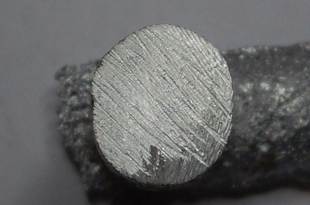
Figure 5. Sectioned Sprue (Solid Metal with no Porosity)
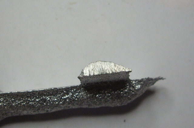
Figure 6. Sectioned Gate (Too small but Solid with no Porosity)
The cause of the major void and minor sink has been attributed to a lack of an adequately sized and positioned riser, not helped by inadequate flux, poor gating, inadequate sprue choking, and maybe too much moisture and/or clay in the sand.
Looking at Figure 6 you can see that the runner (the horizontal metal) only extends a short distance (say 15 mm) beyond the gate (sectioned). This needs to be at least 25 mm to effectively trap any dross.
I was hoping that the runner would serve as a riser but the gate section was too small and and in the wrong location (not connecting the thickest mould section). The gate probably froze off (solidified) while the bulk of the metal in the mould cavity was still liquid. If the gating had been adequate then I would have expected to see a depression at the top centre of the sprue as molten metal was drawn into the mould to compensate for shrinkage.
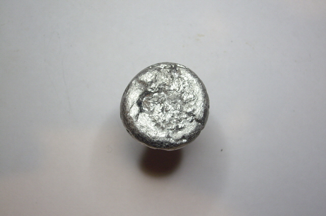
Figure 9. Top of Sprue (almost no Shrinkage where there should be some)
While my gating was not ideal the void and sinks have occurred on three sides and the bottom of casting. If the cause was entirely an inadequate riser then I would have expected these defects to be sink marks near the top of the casting. The top was actually the cleanest face of the casting.
Many molten metals absorb gases (particularly hydrogen in the case of aluminium and oxygen in the case of silver). As the metal solidifies the gas is released resulting in bubbles causing spitting and porosity. In future I will apply flux after removing the dross from the molten charge and then use a degassing agent immediately before the pour.
Other folk have used Sodium or Potassium Chloride as a flux and Sodium Carbonate as a degassing agent and to reduce the metal viscosity. Apparently Borax is not an appropriate flux for aluminium. I can understand how Sodium or Potassium Chloride could be an effective flux. These salts melt at 801 and 770°C respectively and will form a molten layer over the aluminium (670 to 815°C casting temperature range) preventing gas absorption from the atmosphere above the crucible.
I’m not quite so sure of the degassing potential of Sodium Carbonate. Its thermal decomposition products are Sodium Oxide and Carbon Dioxide. Degassing of aluminium usually involves either purging with inert gasses (Nitrogen and Argon), or oxidation of the absorbed Hydrogen using oxidizing agents such as Chlorine which reacts readily with Hydrogen to form Hydrochloric Acid. Calcium Hypochlorite (a principle consistent of granular pool chlorine which produces Chlorine on thermal decomposition) might be more effective than purging with Carbon Dioxide.
During the continuous pour the metal disappeared so quickly into the mould that I could not keep the sprue choked (filled with metal). I clearly need to think again about the dimensions and location of the gating system (sprue, runner, gate and riser).
I’m busy with other stuff for a few weeks, but I’ll be attempting some more casting soon. Please visit again to see how I get on.
Click here to move on to my attempts at systematic rigging design.
|